
Hollow-core photonic crystal fiber gas cell and method for preparing the same

a photonic crystal fiber and gas cell technology, applied in the field of gas cell, can solve the problems of multi-mode interference, difficult implementation of the method, and the cleavage of the hollow crystal fiber, and achieve the effects of reducing the background oscillation, reducing the difficulty of recurrence, and being easy to realize and repea

Active Publication Date: 2017-04-20
SHANGHAI INST OF OPTICS & FINE MECHANICS CHINESE ACAD OF SCI
View PDF2 Cites 9 Cited by
  • Summary
  • Abstract
  • Description
  • Claims
  • Application Information

AI Technical Summary

Benefits of technology

The present invention provides a hollow-core photonic crystal fiber gas cell that eliminates the Fabry-Pérot interference fringes in the background noise of the transmission spectrum and reduces the corresponding background noise oscillations in the transmission spectrum. Compared with existing technology, the gas cell has the following advantages: 1. The collapsed end of the hollow-core photonic crystal fiber is polished, cut, or coated with a membrane, after forming the collapsed end, which reduces the Fabry-Pérot fringes in the background oscillations in the transmission spectrum. 2. The treatment of the collapsed end of the hollow-core photonic crystal fiber being polished, cut, or coated with a membrane, after forming the collapsed end, is simple, convenient, easy to realize and repeated. 3. One end of the hollow-core photonic crystal fiber gas cell has been well fixed with the photonic detector after the collapse treatment, which prevents the space filter effect caused by the coupling of the optic fiber with the finite fiber core diameter and decreases the background oscillations in the transmission spectrum.

Problems solved by technology

However, it is very difficult to cleave the hollow-core photonic crystal fiber with slant angles, thus, the method is difficult to implement.
However, a multi-mode light field exists in the hollow-core photonic crystal fiber due to the specific structure of the hollow-core photonic crystal fiber and limitation on the manufacture method, which further causes the change in distribution of the far-field light spots by the multi-mode interference.
In these prior arts ([I], [II], and [III]) which use fusion splicing or adapting the output end of the hollow-core photonic crystal fiber with the single mode optic fiber have one common problem: the finite fiber core diameter between the single mode optic fiber and the hollow-core photonic crystal fiber equals to adding a space filter into the gas cells, which will cause additional background oscillations that make the frequency stability deteriorated.

Method used


Image

  • Hollow-core photonic crystal fiber gas cell and method for preparing the same
  • Hollow-core photonic crystal fiber gas cell and method for preparing the same
  • Hollow-core photonic crystal fiber gas cell and method for preparing the same

Examples


first embodiment

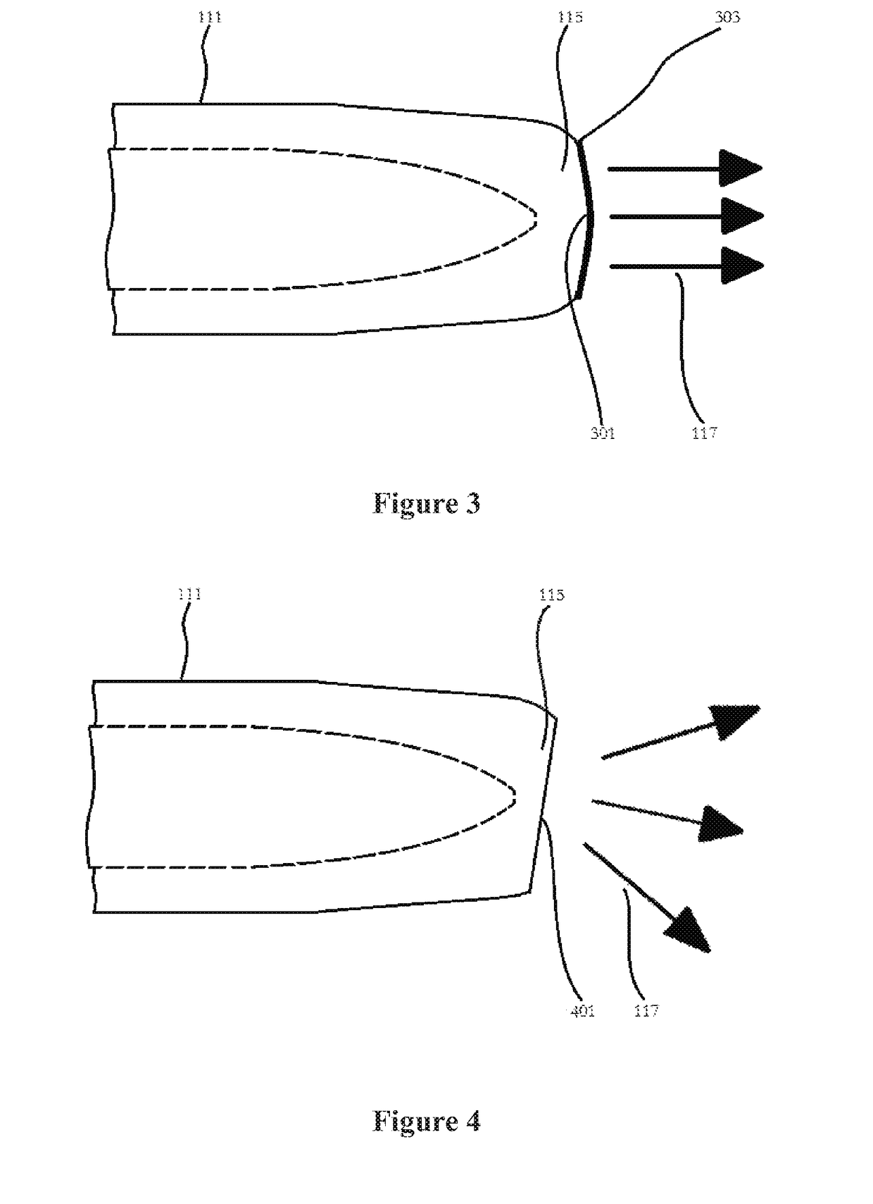
[0043]FIG. 3 shows the hollow-core photonic crystal fiber gas cell of the present invention. The figure partially shows the output end 115 of the hollow-core photonic crystal fiber 111. In the embodiment, the output end 115 has been polished to form a surface 301 with a particular shape that may focus the transmission light 117 to be parallel. The surface 301 has also treated with an anti-reflective 303 coating.

second embodiment

[0044]FIG. 4 shows the hollow-core photonic crystal fiber gas cell of the present invention. The figure illustrates the output end 115 of the hollow-core photonic crystal fiber 111. In the embodiment, the output end 115 has been cut in a slant angle to form a tilted surface 401, which reduces reflection light from the surface of output end 115, and further reduces background oscillations caused by the Fabry-Pérot fringes in the transmission spectrum.

third embodiment

[0045]FIG. 5 shows the hollow-core photonic crystal fiber gas cell of the present invention. The Figure partially shows the output end 115 of the hollow-core photonic crystal fiber 111 and a focusing lens 501. In the embodiment, the output end 115 has been cut at an angle on the surface to form a tilted surface 401 and then the tilted surface 401 is coated with an anti-reflective coating 503. The focusing lens 501 is fixed between the output end 115 and the photodetector 121.

[0046]In these three embodiments, the anti-reflective coating is optional on the surface of the output end after being cut or polished. The anti-reflective coating may further reduce the Fresnel reflection and eliminates the Fabry-Pérot fringes while increase the complexity of processing.

[0047]FIG. 6(a) shows the structure of the hollow-core photonic crystal fiber gas cell and the measured transmission spectra. The upper portion of FIG. 6(a) shows the structure of a conventional hollow-core photonic crystal fibe...


PUM

PropertyMeasurementUnit
stabilityaaaaaaaaaa
lengthaaaaaaaaaa
volumeaaaaaaaaaa

Abstract

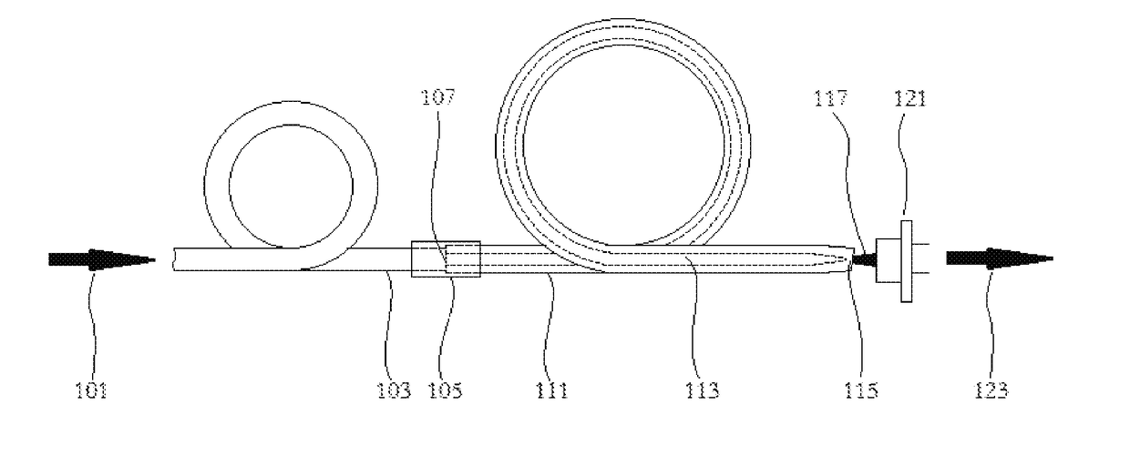
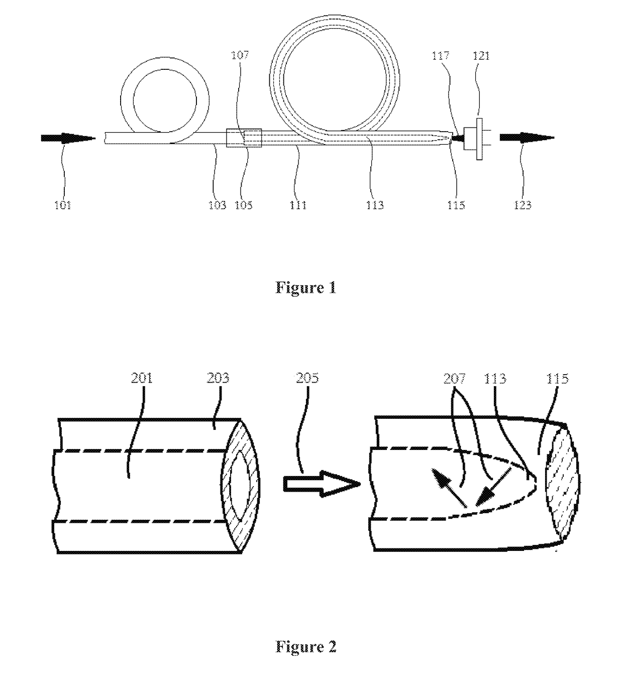
A hollow-core photonic crystal fiber gas cell and method for preparing the same. The hollow-core photonic crystal fiber gas cell comprises a single-mode fiber, a fiber splicing protection sleeve, a hollow-core photonic crystal fiber, and a photoelectric detector. One end of the single-mode fiber is fusion spliced with one end of the hollow-core photonic crystal fiber to form a fusion splice and seal one end of the hollow-core photonic crystal fiber gas cell. The fiber splicing protection sleeve covers and protects the fusion splice. The other end of the hollow-core photonic crystal fiber is processed into an output end by fusion sealing, and the surface of the output end faces, but is not parallel to, a detection surface of the photoelectric detector.

Description

CROSS-REFERENCE TO RELATED APPLICATIONS[0001]The subject application is a continuation-in-part of PCT / CN2014 / 083684 filed on August 5, 2014, which claims priority on Chinese patent application 201410321070.7 filed on Jul. 7, 2014 in China. The contents and subject matter of the PCT international application and Chinese priority application are incorporated herein by reference.FIELD OF THE INVENTION[0002]The present invention relates to the gas cell, particularly, a hollow-core photonic crystal fiber gas cell and method for preparing the same.DESCRIPTION OF THE RELATED ART[0003]A laser with certain frequency and high stability is required in the fields of gas absorption spectrum analysis, laser frequency stabilization, cold atomic clocks, et al. A tunable diode laser with frequency stabilization using the gas absorption line as the frequency reference is used for the purpose.[0004]The gas cell is an essential component in the laser for gas absorption line based frequency stabilizatio...

Claims


Application Information

Patent Timeline
Patent Type & Authority Applications(United States)
IPC IPC(8): G02B6/02G02B6/255G01N21/03
CPCG02B6/02323G01N2201/0846G02B6/255G01N21/03G02B6/4207G01N21/39G02B6/02328G01N2021/399
Inventor CAI, HAIWENCHEN, ZEHENGYANG, FEIGENG, JIANXINCHEN, DIJUNCHEN, WEIBIAO
Owner SHANGHAI INST OF OPTICS & FINE MECHANICS CHINESE ACAD OF SCI
Learn More