Electric motor
a technology of electric motors and motors, applied in the direction of dynamo-electric machines, magnetic circuit shapes/forms/construction, structural associations, etc., can solve the problem of relative complexity in manufacturing, and achieve the effect of compact and robus
- Summary
- Abstract
- Description
- Claims
- Application Information
AI Technical Summary
Benefits of technology
Problems solved by technology
Method used
Image

Examples
first embodiment
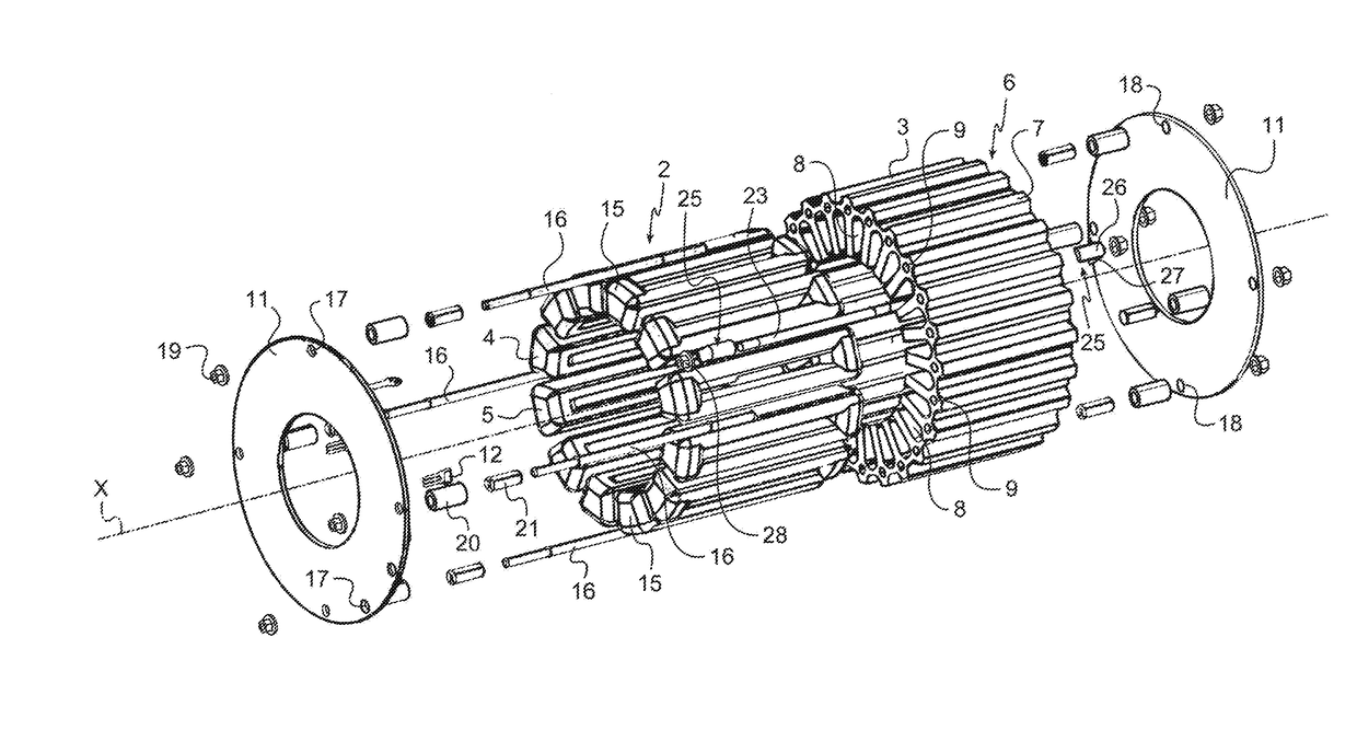
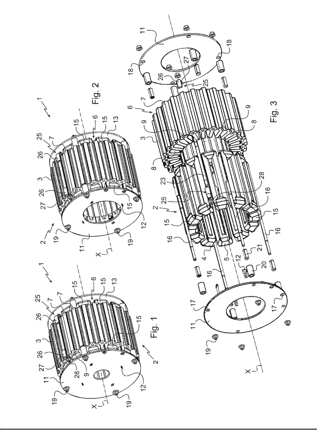
[0019]With reference to FIGS. 1 to 3, the electric motor 1 according to the invention comprises a casing of cylindrical overall external appearance (which has not been depicted), inside which a fixed stator 2 and a rotor (not depicted) rotationally driven about an axis X are incorporated.
[0020]The stator 2 comprises a body 3, a first coil assembly 4 and a second coil assembly 5 which is distinct from and magnetically not coupled to the first coil assembly 4.
[0021]The body 3 of the stator 2 has a tubular overall shape with an internal surface that is substantially cylindrical in order to accommodate the rotor and an external surface that is substantially cylindrical. The body 3 is made up of a plurality of laminations forming a frame and stacked in an axial direction (in this case along the axis X).
[0022]The body 3 of the stator 2 is made in one piece in this embodiment and comprises a plurality of radial sectors 6 which are evenly distributed about the circumference of the body 3 of...
second embodiment
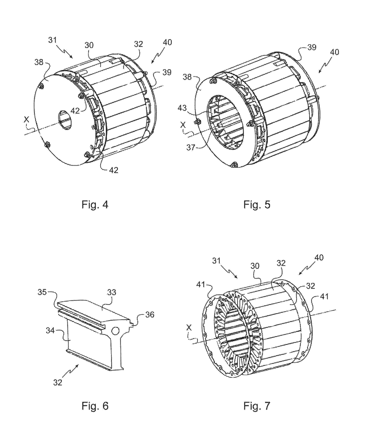
[0039]With reference to FIGS. 4 to 7, the electric motor according to the invention 40 comprises a stator 31 comprising a hollow body 30 of cylindrical external shape.
[0040]The body 30 is made up of a plurality of laminations forming a frame and stacked in an axial direction (in this instance along the axis X).
[0041]In the second embodiment of the invention, the body 30 of the stator 31 of the electric motor 40 is made up of the assembly of distinct radial segments 32 extending over the entire length of the body 30. Each radial segment 32 comprises a base 33 defining a circular sector and a main section 34. A groove 35 and a rib 36 are formed on the base 33 of each radial segment 32. The radial segments 32 are assembled by means of the groove 35 and of the rib 36 of the base 33 of each radial segment 32 to form the body 30 of the stator 31.
[0042]When the radial segments 32 are assembled, the circular sectors of the bases 33 define the cylindrical exterior shape of the body 30 of the...
third embodiment
[0044]In the invention, the body of the stator is made up of a plurality of laminations forming a frame and stacked in an axial direction (in this instance, along the axis X).
[0045]Each lamination comprises fixing holes. When the laminations are stacked, the fixing holes are positioned facing one another so as to form housings that extend over the entire length of the body. The rods emerge from an upper lamination of the body and from a lower lamination of the body to be fixed to the upper lamination and to the lower lamination using fixing means once again involving nuts. Alternatively, the annular fixing rings of the second embodiment and the spacer pieces may also be used with the rods to assemble the laminations and the electric boards.
[0046]It will be noted here that the rods may also act as end stops for the translational movement of the electric motor or as heat bridges to remove the heat generated by the operation of the motor.
[0047]The invention is not restricted to the par...
PUM
 Abstract
Description
Claims
Application Information
 - R&D
- Intellectual Property
- Life Sciences
- Materials
- Tech Scout
- Unparalleled Data Quality
- Higher Quality Content
- 60% Fewer Hallucinations
Browse by: Latest US Patents, China's latest patents, Technical Efficacy Thesaurus, Application Domain, Technology Topic, Popular Technical Reports.
© 2025 PatSnap. All rights reserved.Legal|Privacy policy|Modern Slavery Act Transparency Statement|Sitemap|About US| Contact US: help@patsnap.com