
Remote monitoring for hydraulic fracturing equipment

a hydraulic fracturing and remote monitoring technology, applied in the direction of positive displacement liquid engines, television systems, borehole/well accessories, etc., can solve the problems of permanent damage to the lungs, ceramics can be very harmful to inhalation, and operation can be dangerous for operating personnel

Active Publication Date: 2017-04-06
US WELL SERVICS LLC
View PDF0 Cites 52 Cited by
  • Summary
  • Abstract
  • Description
  • Claims
  • Application Information

AI Technical Summary

Benefits of technology

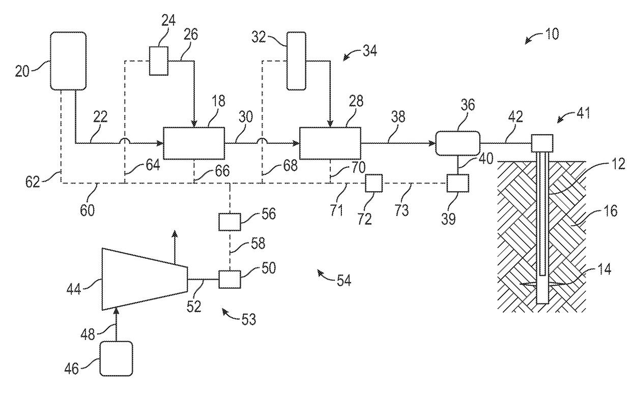
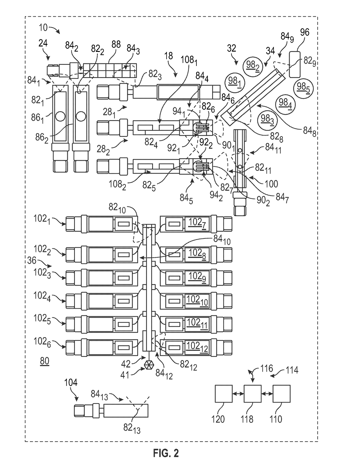
This patent describes a hydraulic fracturing system for fracturing a subterranean formation. The system includes a pump, hydraulic fracturing components, and a monitoring system. The monitoring system includes a camera, controller, display, and human machine interface for monitoring hydraulic fracturing components and pump components in real-time. The monitoring system can capture and transmit images of the hydraulic fracturing system to enable remote monitoring. The images can be viewed in a passenger compartment or on a trailer. The monitoring system can selectively capture and transmit images of specific hydraulic fracturing components or pump components. The hydraulic fracturing components can include a chemical tanker, hydration unit, hopper, blender, and acid tanker. The pump components can include intake piping, discharge piping, hoses, fittings, and valves. The monitoring system can capture and transmit images of a silica exposure zone or an opening to a vessel containing proppant, acid, or chemicals. The hydraulic fracturing system components can be disposed in areas where there is a greater possibility of personal injury than where the images are being viewed. The monitoring system can selectively capture and transmit images of different hydraulic fracturing components or pump components.

Problems solved by technology

Such operation can be dangerous to operating personnel.
For example, moving proppant into the blender unit can generate silica dust which, if inhaled by personnel, can cause permanent damage to the lungs.
Ceramic can be very harmful to inhale, and typically consists of very fine particles that become airborne and are difficult to filter out.
Resin coated sand is the most dangerous and harmful to inhale since the resin coating can chip off and become airborne dust particles.
Silica itself is very harmful to inhale as well.
Other components, such as chemicals, can be damaging and present hazards as well.
One dangerous source of chemical contact comes from residue on tankers, trailer decks, reused hoses and camlock fittings, or leaky valves.
In addition, there is always a risk for a major hose or chemical pump failure, or a tank / tote puncture.
Some chemicals (such as, for example the viscosifier guar gel, and some friction reducers) can be hazardous because of how slick and slippery they are.
Thus, a small amount on the skin, clothing, ground, or equipment can cause personnel to slip and fall, or lose their grip while climbing ladders, leading to injuries.
In addition, chemicals such as acids and breakers (for breaking down viscosifiers) are extremely corrosive to skin, damaging to inhale, can cause blindness, and other immediate hazards.
Chemicals such as breakers are also very flammable, which becomes a hazard if there is a chance of contact with, for example, diesel fuel or gasoline.
Biocides can be very damaging to living tissue, especially if ingested or inhaled.
Additional chemicals that are dangerous if ingested or inhaled include stabilizers, pH buffers, and inhibitors.
In addition to the above, hydraulic fracturing operations can be dangerous for operating personnel because of high pressure and high voltage equipment.
If the pipes fail, they can explode, causing shrapnel to fly.
Hazards can result from breaker or cable coupler failures, or even natural gas vapors entering the area.

Method used


Image

  • Remote monitoring for hydraulic fracturing equipment
  • Remote monitoring for hydraulic fracturing equipment
  • Remote monitoring for hydraulic fracturing equipment

Examples


Embodiment Construction

[0026]The method and system of the present disclosure will now be described more fully hereinafter with reference to the accompanying drawings in which embodiments are shown. The method and system of the present disclosure may be in many different forms and should not be construed as limited to the illustrated embodiments set forth herein; rather, these embodiments are provided so that this disclosure will be thorough and complete, and will fully convey its scope to those skilled in the art. Like numbers refer to like elements throughout. In an embodiment, usage of the term “about” includes + / −5% of the cited magnitude. In an embodiment, usage of the term “substantially” includes + / −5% of the cited magnitude.

[0027]It is to be further understood that the scope of the present disclosure is not limited to the exact details of construction, operation, exact materials, or embodiments shown and described, as modifications and equivalents will be apparent to one skilled in the art. In the ...


PUM


Abstract

A hydraulic fracturing system for fracturing a subterranean formation including a pump in communication via pump components with a wellbore that intersects the formation, and that pressurizes fluid in the wellbore, the fluid comprising a fracturing fluid slurry. The system further includes hydraulic fracturing system components for making the fracturing fluid slurry, and a monitoring system that selectively captures and transmits real time images of at least one of the hydraulic fracturing system components or pump components to enable remote monitoring of the at least one of the hydraulic fracturing system components or pump components.

Description

CROSS REFERENCE TO RELATED APPLICATIONS[0001]This application claims priority to and the benefit of, co-pending U.S. Provisional Application Ser. No. 62 / 242,566, filed Oct. 16, 2015 and is a continuation-in-part of, and claims priority to and the benefit of co-pending U.S. patent application Ser. No. 15 / 202,085, filed Jul. 5, 2016, which claimed priority to and the benefit of Ser. No. 13 / 679,689, filed Nov. 16, 2012, which issued as U.S. Pat. No. 9,410,410 on Aug. 9, 2016; the full disclosures of which are hereby incorporated by reference herein for all purposes.BACKGROUND OF THE INVENTION[0002]1. Field of Invention[0003]The present disclosure relates to hydraulic fracturing operations in a subterranean formations. In particular, the present disclosure relates to a hydraulic fracturing system with imaging devices that are strategically positioned to remotely monitor portions of the system.[0004]2. Description of Prior Art[0005]Hydraulic fracturing is a technique used to stimulate pr...

Claims


Application Information

Patent Timeline
IPC IPC(8): E21B43/26H04N7/18
CPCH04N7/185E21B43/26E21B43/267F04B17/03F04B19/22F04B47/02F04B49/20F04B51/00F04B15/02F04B49/06E21B43/2607F01D15/08F01D15/10F02C3/22H02P23/00
Inventor OEHRING, JAREDHINDERLITER, BRANDON N.
Owner US WELL SERVICS LLC
Learn More