
Header with Middle Belt and Additional Grain Loss Prevention Means

a technology of head belt and middle belt, applied in the direction of mowers, agriculture tools and machines, agriculture, etc., can solve the problems of belt no longer revolving in a correctly driven manner, the strip applied to the revolving middle belt is not sufficient, and the crop is lost. , to achieve the effect of reducing the flexing work, satisfying the service life, and reducing the average tensile load

Inactive Publication Date: 2017-04-06
CARL GERINGHOFF GMBH & CO KG
View PDF0 Cites 7 Cited by
  • Summary
  • Abstract
  • Description
  • Claims
  • Application Information

AI Technical Summary

Benefits of technology

The patent describes a device that prevents grain kernels or oilseeds from rolling over the edges of a conveyor belt during processing. This is achieved through the use of elevations on the belt, which stop the grains from moving further. Additionally, the patent describes the use of strips on the belt that have an undulating shape, which help to pull material out of regions where it is not actively being processed by the device. These technical effects improve the efficiency and accuracy of the grain and oilseed processing operations.

Problems solved by technology

This applies in particular to grain kernels, which are essential to the harvest yield but which can very easily roll away over the edges of the middle belt, and thus be lost in terms of the crop, in the event of shocks, wind, oblique positions of the header during harvesting, material accumulations and other disruptions in the harvesting process or material flow.
It has been found that the strips applied to the revolving middle belt are not sufficient to prevent grain losses over the lateral edges of the middle belt under all harvesting conditions.
The oil that emerges from the grains as a result adheres to the inner surface of the revolving belt and causes slippage of the driven deflecting roller on the inner side of the revolving belt, such that the belt no longer revolves in a correctly driven manner.
The oil that adheres to the inner side of the revolving belt may furthermore become resinous in the air, and thereby cause the revolving belt to stick to the deflecting roller and give rise to vibratory, rough running of the revolving middle belt.
The support parts cannot be fastened to a middle belt because the belt material is too thin in relation to the conveyor belts.
The support parts are also not flexible enough to revolve around the narrow deflecting rollers that are used in the case of belt-type conveyors, and in particular in the case of middle belts, over a relatively long period of time without sustaining damage.
Furthermore, the intermediate spaces at the support parts are too large to be able to effectively retain grains.

Method used


Image

  • Header with Middle Belt and Additional Grain Loss Prevention Means
  • Header with Middle Belt and Additional Grain Loss Prevention Means
  • Header with Middle Belt and Additional Grain Loss Prevention Means

Examples


Embodiment Construction

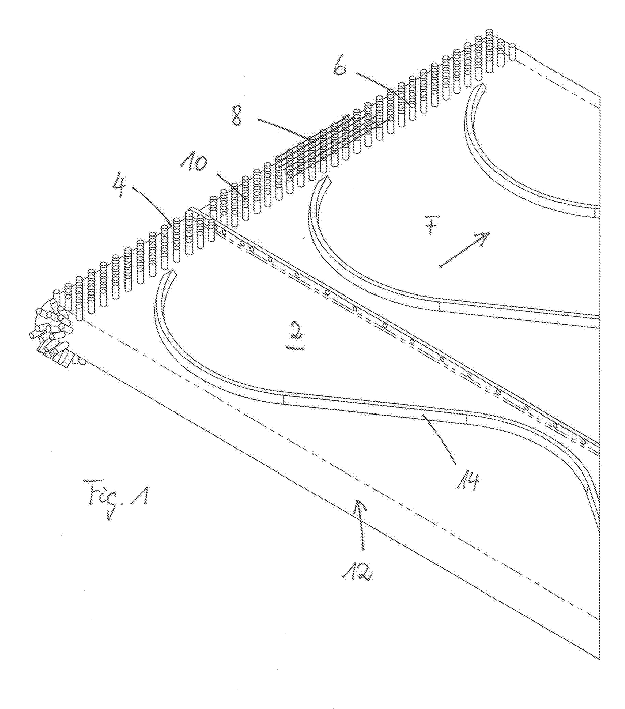
[0029]FIG. 1 shows a partial view of a middle belt in a perspective front view.

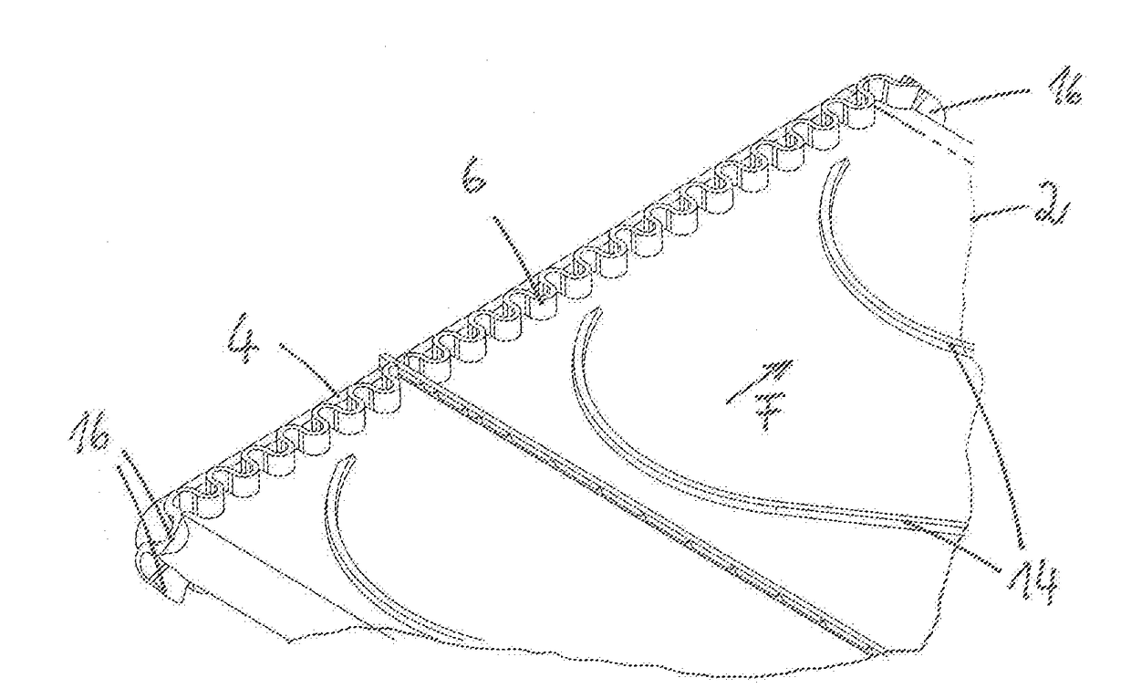
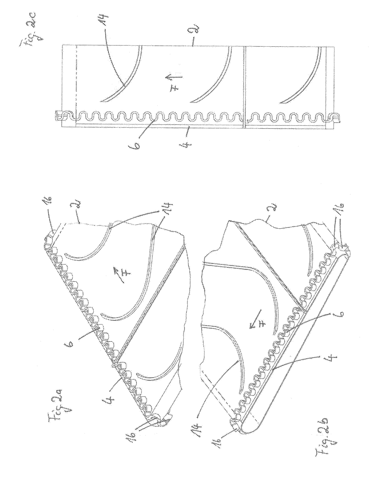
[0030]FIG. 1 shows a detail of a middle belt 2 in a perspective view from above. The middle belt 2 is driven in continuous circulating fashion in a conveying direction F, counter to the direction of travel of the harvesting machine into the standing crop. The middle belt 2 has lateral edges 4. In a draper header, the cut crop is conveyed to the middle belt 2 by lateral belt-type conveyors which discharge the crop past the lateral edges 4 onto the top side of the middle belt 2.

[0031]FIG. 1 shows six rows 8 of elevations 6 on the lateral edge 4 of the middle belt 2. In the embodiment, the elevations 6 are composed of molded bodies 10 which have a cylindrical basic shape. The molded bodies 10 are lined up with one another at uniform intervals. The rows 8 are offset with respect to one another in staggered fashion such that the molded bodies 10 of one row cover in a transverse direction a gap between the mold...


PUM


Abstract

A header for harvesting agricultural crop is designed to be mounted on a harvesting machine and has a support frame with a cutter bar arranged on the front side and blades fastened thereto. Conveying elements for transporting away the cut stalk material include at least two belt conveyors conveying the crop transversely relative to the travel direction and a central belt conveyor as a middle belt that conveys counter to the travel direction. A drive drives the cutter bar and the conveying elements. In order to better protect the middle belt against grain losses over the lateral edge of the revolving belt, the middle belt has, at lateral edges on its outwardly pointing surface, a grain-blocking elevation, respectively.

Description

BACKGROUND OF THE INVENTION[0001]The present invention relates to a header for agricultural crop, wherein the header is provided for mounting on a harvesting machine. The header comprises a support frame, a cutter bar arranged on the front side and having blades fastened thereto, and conveying elements for conveying away the cut stalk material. The conveying elements comprise at least two belt-type conveyors which convey the crop transversely with respect to the direction of travel of the header during harvest, and further comprise a centrally arranged belt-type conveyor as a middle belt, which conveys counter to the direction of travel of the header. Drive means for driving the cutter bar and the conveying elements are provided.[0002]A header of the aforementioned kind is known from U.S. Pat. No. 7,444,798. The middle belt has, on its outwardly pointing surface, strips which are applied so as to be spaced apart from one another and which are obliquely inclined in trailing fashion t...

Claims


Application Information

Patent Timeline
IPC IPC(8): A01D34/40A01D57/20A01D34/14B65G15/46
CPCA01D34/40B65G15/46A01D2101/00A01D34/14A01D57/20B65G15/42
Inventor WEBERMANN, DIRKSCHULZE SELTING, STEPHANPOKRIEFKE, MICHAEL
Owner CARL GERINGHOFF GMBH & CO KG
Learn More