Probe holder with spacer

a technology of probe holder and spacer, which is applied in the direction of liquid/fluent solid measurement, instruments, machines/engines, etc., can solve the problems of complex construction and mounting procedures, no longer being able to dismantle assembled components for maintenance or troubleshooting, and being exposed to extreme influences on the fill level measuring device. , to achieve the effect of simple and effective manner

Active Publication Date: 2017-03-30
KROHNE S.A.S.
View PDF2 Cites 3 Cited by
  • Summary
  • Abstract
  • Description
  • Claims
  • Application Information

AI Technical Summary

Benefits of technology

[0007]The object of the invention is to provide a probe holder that realizes a seal against the process area in a simple, but effective manner.
[0008]The above described and derived object is initially achieved in that the spacer is shrunk in the holder housing so that a sealed closure is created between the holder housing and the spacer in the shrunken state. Thus, a sealed closure between the holder housing and the spacer is implemented in a very simple manner without using sealing elements. This has the advantage that—since there is no need for a separate sealing element—there is no wear on sealing elements, which could lead to impairment of a sealing effect. Additionally, the present seal is maintenance-free, mounting of additional parts is no longer necessary. Furthermore, spacer and holder housing no longer have to be prepared for the accommodation of a separate seal, such as the introduction of grooves.
[0010]A particularly preferred design of the probe holder according to the invention is characterized in that at least one seal is arranged between the holder housing and the spacer. The seal is arranged, in particular, between surfaces of the holder housing and of the spacer facing one another that have not been acted upon by a force and pushed together due to the shrinkage. This has the advantage that the seal is not thermally strained during shrinking, since it does not necessarily have to come into contact with a heated surface. This is preferably also implemented so that the seal does not interfere with the actual shrinking, in particular the seal created by shrinkage. Thus, the seal is not located in the area of the sealed contact created by shrinkage between the holder housing and the spacer. In particular, the seal is affixed on the end of the spacer on the interior side of the housing, i.e., on a surface of the spacer that faces the interior space of the holder housing.
[0011]The arrangement of this additional, separate seal is primarily an advantage when shrinkage is relaxed or completely suspended during an extreme thermal load of the fill level measuring device. If unpredicted changes of the state in the process area occur, for example, a large increase in temperature, and if the maximum temperature is greater than a critical temperature so that the holder housing expands, this can lead to the spacer no longer being ideally shrunk in the holder housing and thereby the previously achieved tightness being suspended. The additional seal is provided in order to avoid a penetration of the medium into the fill level measuring device or to avoid an influence of the process area conditions on the fill level measuring device, in particular the electronics of the fill level measuring device.

Problems solved by technology

Depending on the type of medium to be measured or the type of surrounding conditions, i.e., the conditions prevalent in the process area, fill level measuring devices can be exposed to extreme influences.
Solutions are known that usually use a plurality of seals and screw connections, in part with permanent material connections, which often leads to very elaborate construction and mounting procedures and sometimes has the disadvantage that assembled components can no longer be dismantled for maintenance or troubleshooting, at least not without destruction.

Method used


Image

  • Probe holder with spacer
  • Probe holder with spacer
  • Probe holder with spacer

Examples


Embodiment Construction

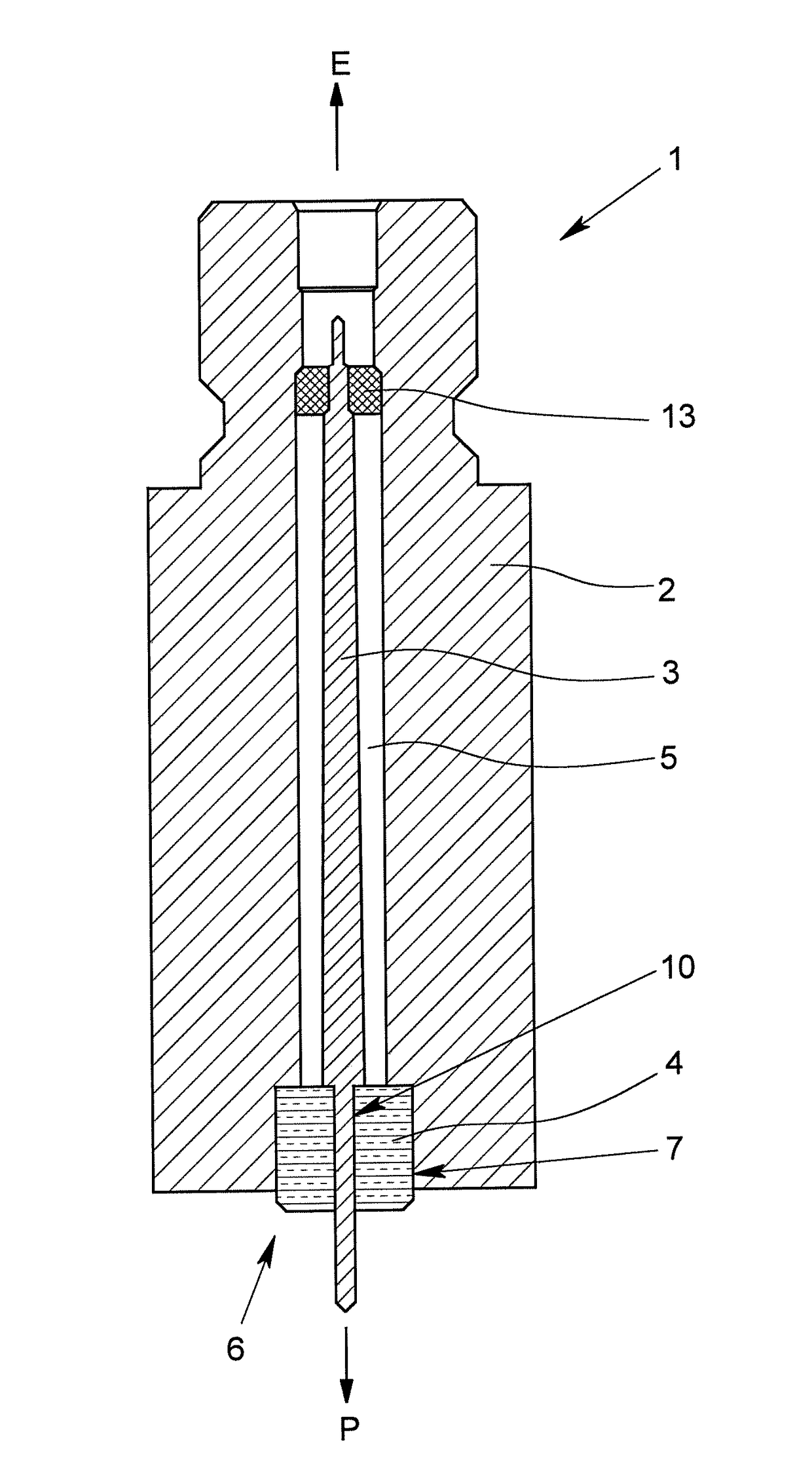
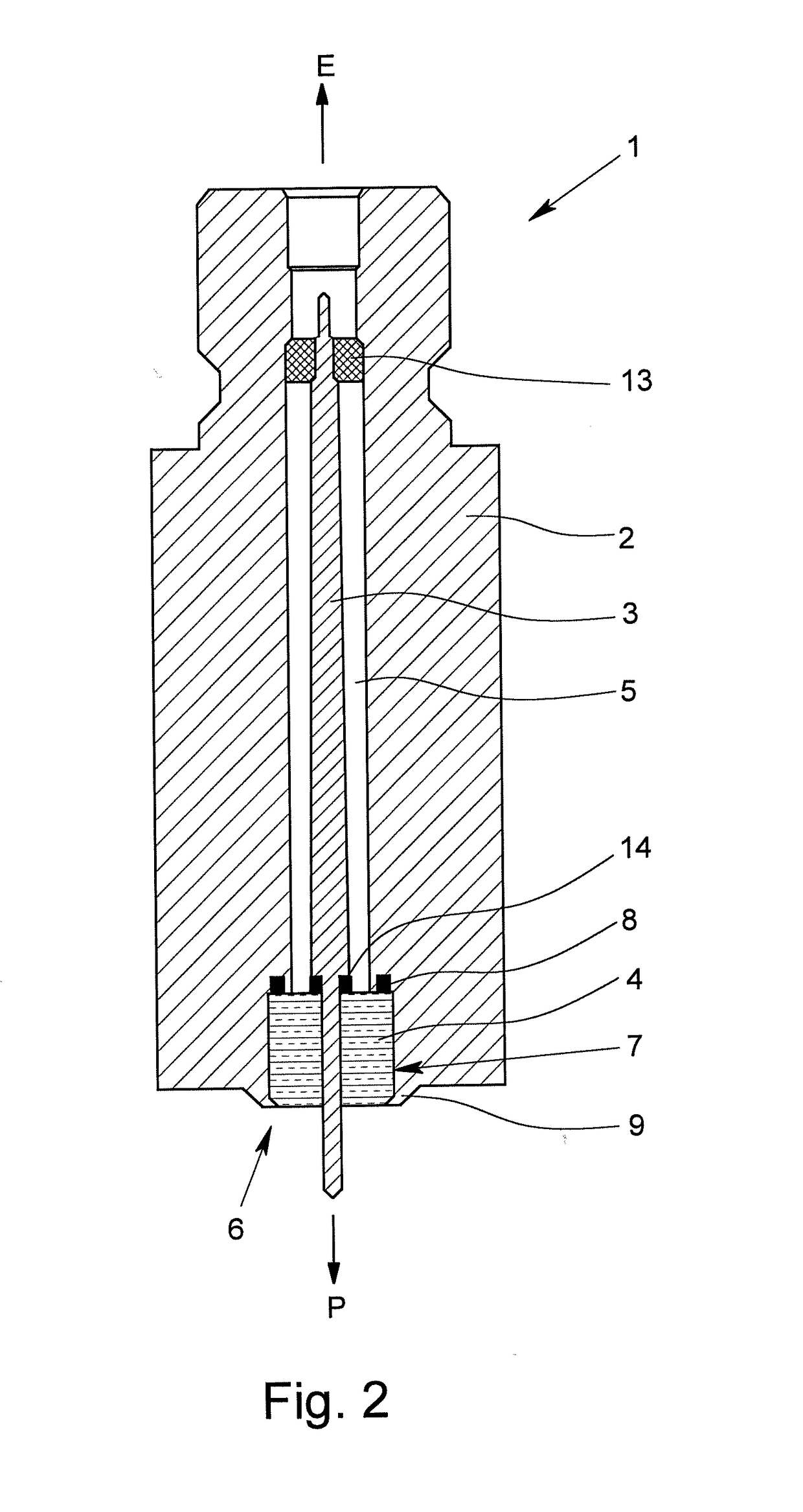
[0028]A probe holder 1 according to the invention for a fill level measuring device operating with the radar principle is depicted in FIG. 1. The probe holder 1 comprises a holder housing 2 and a signal conductor 3. The signal conductor 3 is led out of the interior space 5 of the holder housing 2 through a wherein opening 6 of the holder housing 2 into the wherein exterior space. The process side exterior space is not depicted in the form of a closed process area, however is illustrated by the arrow designated with P.

[0029]The signal conductor 3 is used for guiding emitted and / or received signals, wherein an emitted signal is generated by conventional electronics that are not shown and are coupled into the signal conductor on the electronics side—indicated by an arrow designated with E. A received signal is coupled into the signal conductor 3 on the process area side and led to electronics implementing an evaluation unit. In order to guide the signals, the signal conductor 3 is form...


PUM


Abstract

A probe holder for a fill level measuring device operating with the radar principle has a holder housing, a signal conductor for guiding emitted and / or received signals and a spacer. The signal conductor is led out of the interior space of the holder housing through an opening of the holder housing into a process side exterior space of the holder housing. The spacer is arranged in the opening of the holder housing and keeps the signal conductor spaced from the holder housing in the opening. The probe holder realizes a seal relative to the process area in a simple, but effective manner in that the spacer is held in the holder housing by a shrink-fit so that a sealed closure is created between the holder housing and the spacer in the shrunken-in state.

Description

BACKGROUND OF THE INVENTIONField of the Invention[0001]The invention relates to a probe holder for a fill level measuring device operating with the radar principle having a holder housing, having a signal conductor for guiding emitted and / or received signals and having a spacer, wherein the signal conductor is led out of the interior space of the holder housing through a wherein opening of the holder housing into the process side exterior space of the holder housing, wherein the spacer is arranged in the opening of the holder housing and keeps the signal conductor spaced from the holder housing in the opening.Description of Related Art[0002]Fill level measuring devices that operate using the radar principle are used for measuring fill levels in containers such as, for example, tanks or silos. Often, so-called guided radar systems tare used here, which are based on the principle of time domain reflectometry (TDR); the probe holders mentioned in the introduction are of interest for su...

Claims


Application Information

Patent Timeline
Patent Type & Authority Applications(United States)
IPC IPC(8): G01F23/284
CPCG01S2007/027G01F23/284G01D11/30G01S7/027
Inventor PICHOT, VINCENTPEIGAT, LAURENT
Owner KROHNE S.A.S.
Why Eureka
Try Eureka