Ultrasonic reception signal correction device, ultrasonic measurement apparatus, and ultrasonic reception signal correction method

a technology of ultrasonic signal and correction device, applied in the field of ultrasonic reception signal correction device, ultrasonic measurement apparatus, and ultrasonic reception signal correction method, can solve the problems of hardly obtaining acoustic shadow, reflected waves from a region behind the tissue that strongly reflects ultrasonic waves, and it is difficult to say that the effect of reducing acoustic shadow is sufficiently obtained

Inactive Publication Date: 2017-03-30
SEIKO EPSON CORP
View PDF6 Cites 4 Cited by
  • Summary
  • Abstract
  • Description
  • Claims
  • Application Information

AI Technical Summary

Benefits of technology

The invention proposes a new method for reducing the acoustic shadow caused by reflected waves of ultrasonic waves. The reception signal is corrected by calculating the attenuation correction value and performing a Fourier transform. This method can detect and correct the acoustic shadow without needing a specific region to be identified. In case of multiple reflected waves at different depth positions, the method can extract individual signals and correct them by combining the signals obtained from different extraction periods. This results in a more accurate reception signal with reduced acoustic shadow.

Problems solved by technology

In an ultrasonic measurement apparatus that acquires biological information of a subject using ultrasonic waves, there has been a problem of acoustic shadow.
However, since ultrasonic waves cannot pass through the tissue that strongly reflects the ultrasonic waves, such as a bone or a stone, reflected waves from a region behind the tissue that strongly reflects the ultrasonic waves are hardly obtained.
Accordingly, it is hard to say that the effect of reducing the acoustic shadow is sufficiently obtained.

Method used


Image

  • Ultrasonic reception signal correction device, ultrasonic measurement apparatus, and ultrasonic reception signal correction method
  • Ultrasonic reception signal correction device, ultrasonic measurement apparatus, and ultrasonic reception signal correction method
  • Ultrasonic reception signal correction device, ultrasonic measurement apparatus, and ultrasonic reception signal correction method

Examples


Embodiment Construction

Principle

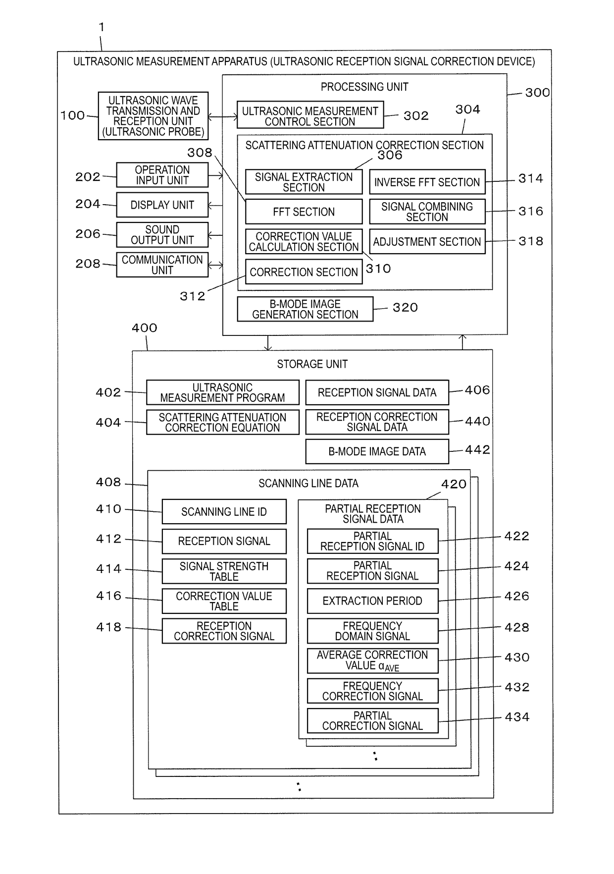
[0031]An ultrasonic measurement apparatus of the present embodiment is a device that measures biological information of a subject using ultrasonic waves. By making ultrasonic waves incident on the subject from an ultrasonic probe (by transmitting ultrasonic waves to the subject from the ultrasonic probe) and performing signal processing on a reception signal of reflected waves (ultrasonic echoes), it is possible to obtain the position information of a structure in the subject or reflected wave data, such as temporal changes in the structure. Not only the reception signal itself but also images of respective modes of so-called A mode, B mode, M mode, and color Doppler mode are included in the reflected wave data. In addition, the ultrasonic measurement apparatus is also an ultrasonic reception signal correction device that corrects a reception signal of attenuated ultrasonic waves to reduce the acoustic shadow.

[0032]In an ultrasonic probe, a plurality of ultrasonic elements ...


PUM


Abstract

An ultrasonic measurement apparatus extracts, from a reception signal, a plurality of partial reception signals according to overlap periods that are set by shifting the time so as to overlap partially. Then, scattering attenuation correction using a scattering attenuation correction value is performed for a frequency domain signal obtained by performing a Fourier transform of each of the plurality of partial reception signals, and an inverse Fourier transform of a corrected frequency correction signal is performed. Then, partial correction signals corresponding to the respective partial reception signals are obtained by performing an inverse Fourier transform. Then, a signal obtained by combining the partial correction signals is set as a reception correction signal after correcting the reception signal. The scattering attenuation correction value is calculated from the signal strength of incident ultrasonic waves and a sum value of the signal strength of the reception signal at each time.

Description

BACKGROUND[0001]1. Technical Field[0002]The present invention relates to an ultrasonic reception signal correction device and the like for correcting a reception signal of reflected waves of ultrasonic waves from a subject.[0003]2. Related Art[0004]In an ultrasonic measurement apparatus that acquires biological information of a subject using ultrasonic waves, there has been a problem of acoustic shadow. Ultrasonic waves incident on the subject propagate through the subject while being reflected on the boundary surface of the body tissue, such as muscles, blood vessels, and bones. Accordingly, it is possible to know the structure of the body tissue from the reception signal of reflected waves (ultrasonic echoes) of the ultrasonic waves. However, since ultrasonic waves cannot pass through the tissue that strongly reflects the ultrasonic waves, such as a bone or a stone, reflected waves from a region behind the tissue that strongly reflects the ultrasonic waves are hardly obtained. A n...

Claims


Application Information

Patent Timeline
IPC IPC(8): A61B8/08A61B8/00A61B5/00A61B8/14G01S15/89G01S7/52
CPCA61B8/5269G01S15/8988A61B8/4444A61B5/7257A61B8/14G01S7/52026A61B8/5207G01S15/8977G06T2207/10132
Inventor WATANABE, RYOKI
Owner SEIKO EPSON CORP
Why Eureka
Try Eureka