Differential pressure transducer assembly with overload protection

a technology of differential pressure transducer and overload protection, which is applied in the direction of fluid pressure measurement by electric/magnetic elements, measuring devices, instruments, etc., can solve the problems of requiring overpressure protection, affecting the accuracy of digital data output, and mechanical sensors of the early 20th century, so as to reduce the internal pressure slightly, increase the internal volume, and eliminate any additional pressure

Active Publication Date: 2017-03-23
TECSIS
View PDF3 Cites 1 Cited by
  • Summary
  • Abstract
  • Description
  • Claims
  • Application Information

AI Technical Summary

Benefits of technology

[0014]The instant design virtually eliminates any additional pressure from being transmitted to the sensor once the overload stop valves engage. In fact, as external pressure is increased the internal pressure decreases slightly. The overload stop valves include O-rings which provide a seal between the valve core and the transducer body in excess pressure events. As the O-rings of the overload stop valves compress with increased pressure, the diaphragm is displaced in such a manner to increase the internal volume, and thus, lower the internal pressure.
[0015]Using a diaphragm is also advantageous compared to using a coiled spring to protect against rapid pressure changes. As the diaphragm deflects to c...

Problems solved by technology

Early sensors were mechanical and could handle higher pressure fluctuations but were not as accurate and did not output digital data.
The modern sensors are more fragile and require overpressure protection.
However, the deformation increases the pressure in the chamber and forces the internal diaphragms to deform.
However, the fill fluids (usually incompressible fluids) present several disadvantages and challenges.
First, fill fluids that escape may contaminate the larger system or create explosion hazards.
Second, the fill fluid is subject to expansion and contraction with temperature, such that the temperature range over which the unit can remain calibrated is limited.
Third, compressibility of the fill fluid further limits the max...

Method used


Image

  • Differential pressure transducer assembly with overload protection
  • Differential pressure transducer assembly with overload protection
  • Differential pressure transducer assembly with overload protection

Examples


Embodiment Construction

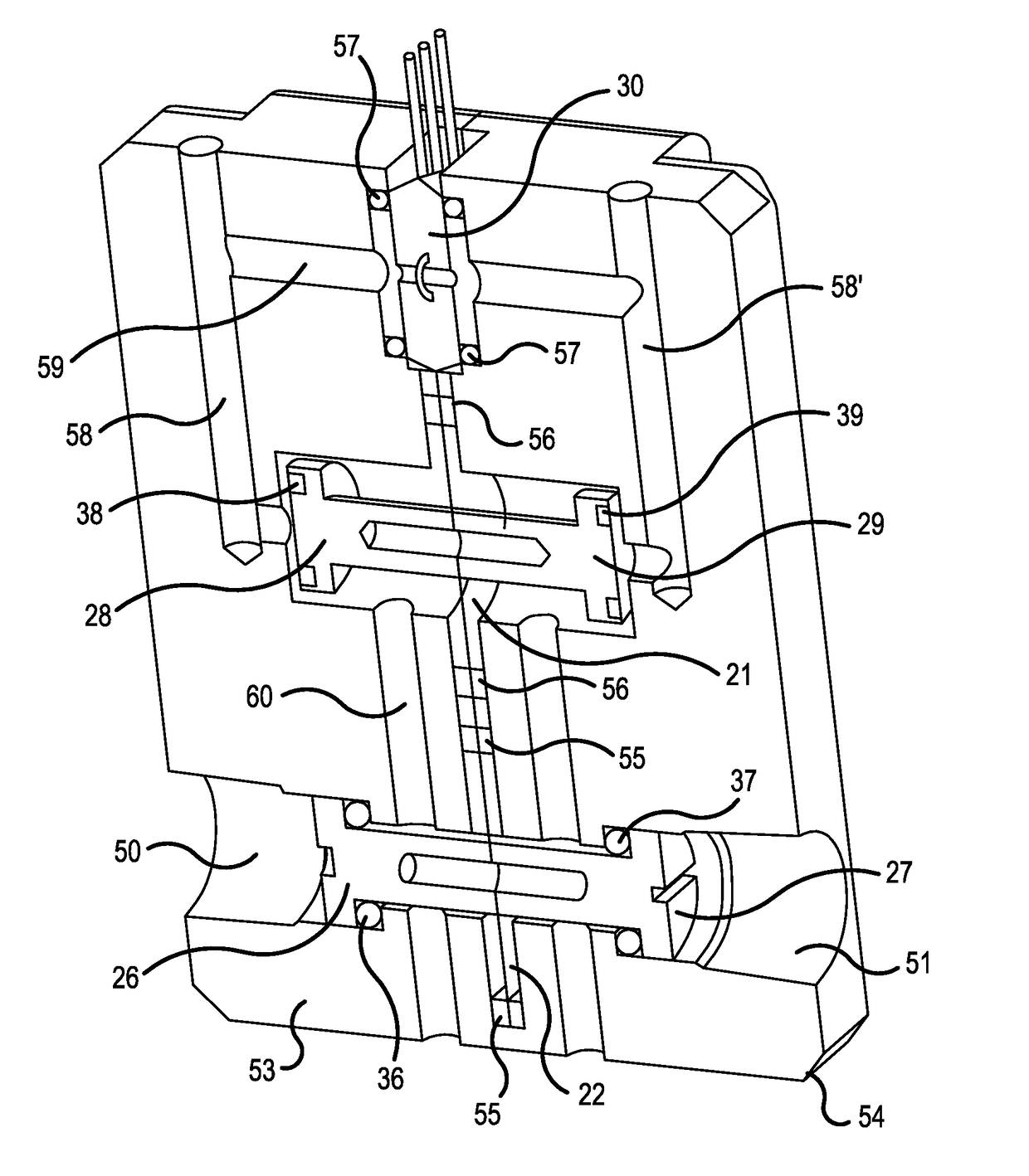
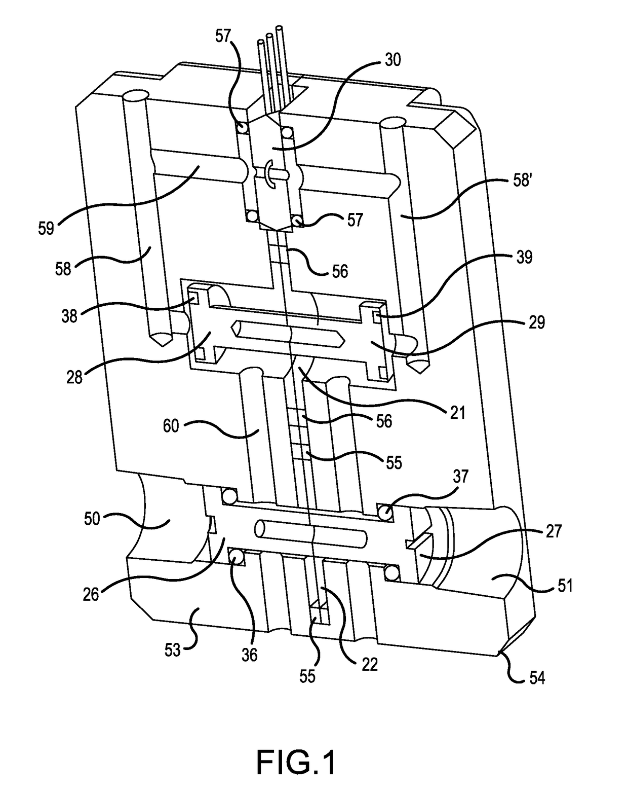
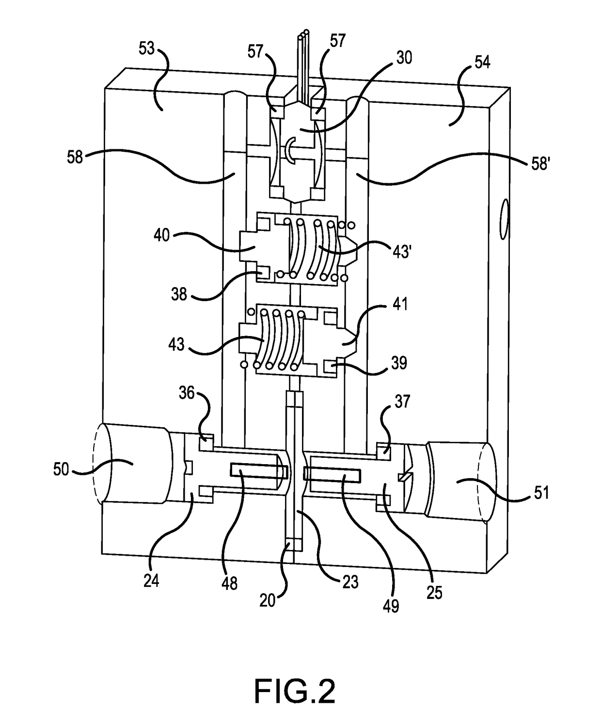
[0023]The device of FIG. 1 provides two diaphragm mechanisms, which protect against pressure increases and decreases. For example, overload stop valves 26 and 27 protect against increasing pressure and overload stop valves 28 and 29 protect against sudden pressure release. Together, the two valves 28 and 29 provide excess pressure protection for a differential pressure sensor 30.

[0024]Each overload stop valve 26, 27, 28 or 29 is seated in an open and unbiased position substantially perpendicular to diaphragm elements 21 or 22. Each overload stop valve 26, 27, 28 or 29 includes a wide end or head, which is seated between a lip in the first pressure port and a main body of the protection device. Each overload stop valve also includes a short end which extends up to the diaphragm element 21 or 22. The diaphragm elements 21 or 22 can be made of, for example, a metal or an alloy, and can be flat or made with a wave structure. However, any other structure which allows and optimizes deflec...


PUM


Abstract

A pressure overload protector for a sensor includes a pressure-filled channel system fillable with fluid or gas, a first overload stop seated in an open position, a first diaphragm at the unseated end of the first overload stop, a second overload stop seated in an open position, a second diaphragm at the unseated end of the second overload stop, a sensor connected to a fluid channel, and a third and fourth overload stop connected by channels to the fluid channel of the sensor and terminating at a fluid exit. The overload protector provides bidirectional over and under pressure protection to the sensor.

Description

FIELD OF THE INVENTION[0001]The present device relates to a differential pressure transducer assembly with overload protection.BACKGROUND OF THE INVENTION[0002]Differential pressure sensors convert pressure fluctuations into electrical signals using piezo-electric or semi-conductor sensors. Early sensors were mechanical and could handle higher pressure fluctuations but were not as accurate and did not output digital data. The modern sensors are more fragile and require overpressure protection.[0003]Over-pressure protection and under-pressure occur frequently in an input / output system or hydraulic system under pressure. Pressure fluctuations, especially in incompressible fluids, can change very quickly. These fast and repeated pressure fluctuations require durable and responsive protection systems.[0004]The disclosure of U.S. Pat. No. 4,072,058 to Whitehead provides a pressure sensor protector that includes two pairs of chambers and two pairs of diaphragms. The first two diaphragms o...

Claims


Application Information

Patent Timeline
IPC IPC(8): G01L19/06G01L13/02G01L9/00
CPCG01L19/0618G01L13/025G01L9/0072G01L9/0052G01F1/34G01L13/00
Inventor TURNER, ROBERTGVANTMAKHER, PAVELOST, REINHOLDYOHR, BRUCEJONES, MARK
Owner TECSIS
Why Eureka
Try Eureka