
Drug Delivery Device with Cap Induced Needle Movement

a technology of a delivery device and a needle movement, which is applied in the field of medical devices, can solve the problems of unspecified volume of the drug, small than intended dose being delivered, and user not being aware of the risks associated with the upcoming injection, so as to eliminate or reduce at least one drawback

Inactive Publication Date: 2017-03-23
NOVO NORDISK AS
View PDF3 Cites 3 Cited by
  • Summary
  • Abstract
  • Description
  • Claims
  • Application Information

AI Technical Summary

Benefits of technology

The invention aims to solve the problems of previous drug delivery devices by eliminating the risk of leakage or clogging, even if the injection needle is not removed between injections. Additionally, it can operate without needing to move the drug reservoir relative to the device housing.

Problems solved by technology

Other injection devices are prefilled when delivered to the user and can only be used until the drug reservoir has been emptied.
Nevertheless, many people choose to re-use the injection needles, and some even use the injection needles several times. If the back needle resides in the drug reservoir during storage of the injection device an unspecified volume of the drug may leak out, either due to dripping or evaporation.
Leakage of drug may lead to a smaller than intended dose being delivered during the following administration, either because the piston as a result has moved distally, leading to an air gap between the piston and the piston washer, or because the leaked drug has been substituted with an air bubble inside the cartridge.
Capillary effects in the needle will continuously replenish the dried out drug, and eventually the crystallisation may clog the injection needle completely and prevent further injections.
However, if, for some reason, the air shot is not performed, e.g. due to negligence from the user, the user will not be aware of the risks associated with the upcoming injection.
However, apart from the addition of a cost-raising metal component dedicated to effect this return the solution entails a complex type of device where the drive mechanism during the administration procedure firstly has to displace the entire cartridge relative to the housing, and subsequently displace the piston relative to the cartridge while the cartridge is fixed with respect to the housing.
It is thus undesirable to additionally take account of a part of the piston rod movement being used to advance the cartridge itself.

Method used


Image

  • Drug Delivery Device with Cap Induced Needle Movement
  • Drug Delivery Device with Cap Induced Needle Movement
  • Drug Delivery Device with Cap Induced Needle Movement

Examples


first embodiment

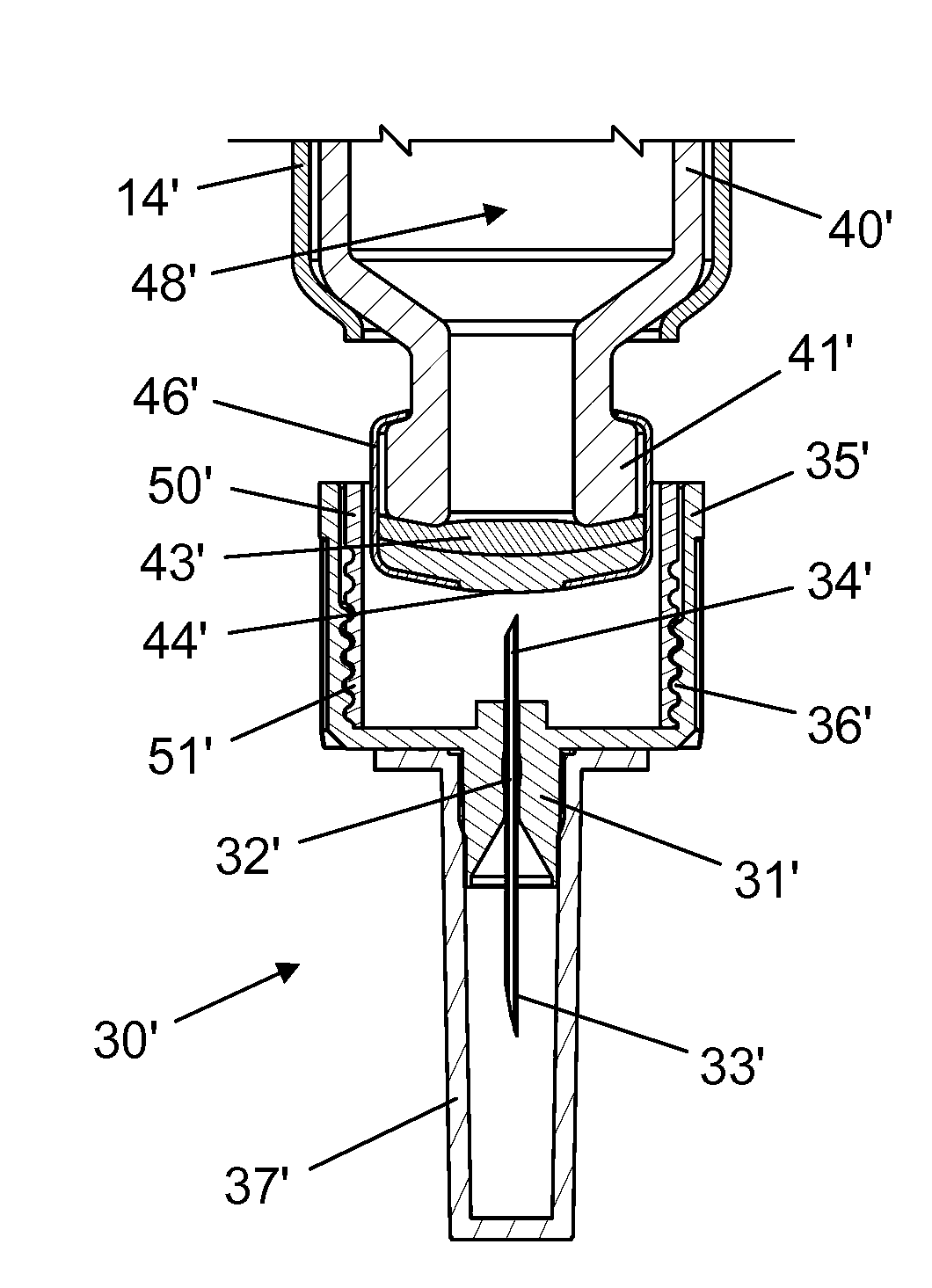
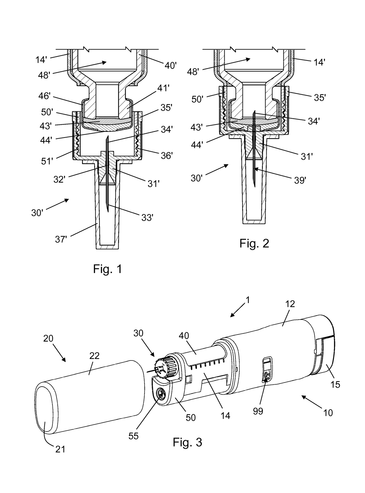
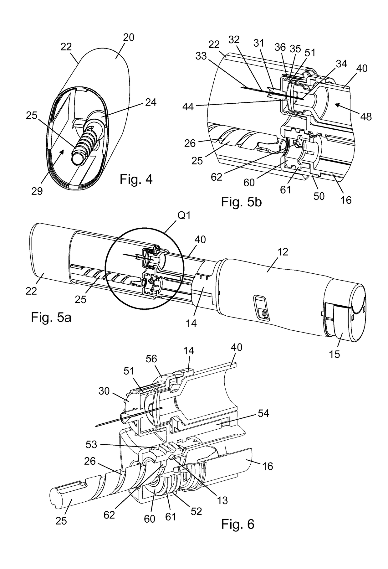
[0079]FIG. 3 is a perspective view of an injection device 1 according to the invention. The injection device 1 comprises a drug delivery unit 10 and a protective cap 20. The drug delivery unit 10 comprises a housing 12 which extends along a general longitudinal axis and accommodates a drug expelling mechanism, a cartridge holder 14 which is axially fixed to the housing 12 and which carries a cartridge 40, and a needle holder 50 to which a needle assembly 30 is removably attached. The needle holder 50 has a bore 55 adapted for reception of a portion of the cap 20, as will be explained in greater detail below. An injection button 15 is provided at the proximal end portion of the housing 12 for activation of the drug expelling mechanism. The injection device 1 is capable of selective dose setting, and the housing 12 thus further accommodates a dose setting mechanism which comprises a scale drum having dose indicia applied to its exterior surface. A window 99 is provided in the housing ...

second embodiment

[0090]FIG. 10 is an exploded perspective view of a distal portion of an injection device according to the invention. The distal portion is composed of a protective cap 120 comprising a cap wall 122, which is closed at one end and open at an opposite end, a needle assembly 130, a needle holder 150 adapted to releasably retain the needle assembly 130, a cartridge holder 114, and a cartridge 140. The cartridge holder 114 is adapted for axial fixation to a tubular housing (not shown), e.g. in a manner conventionally known in the art of injection pens which comprises a proximal end portion of the cartridge holder 114 being retained by a distal end portion of the housing. The housing accommodates a drug expelling mechanism and constitutes together with the cartridge holder 114, the cartridge 140, and the needle holder 150 a drug delivery unit. The cartridge 140 is adapted for axial fixation in the cartridge holder 114 when the cartridge holder 114 is fixed to the housing.

[0091]The cartrid...


PUM


Abstract

A drug delivery device (1, 200) comprising a drug delivery unit (10, 210) comprising a housing (12, 212) extending along a general axis, a variable volume reservoir (40′, 40, 140, 240), and a needle support (50′, 50, 150, 250) for receiving a needle assembly (30′, 30, 130, 230), the needle support (50′, 50, 150, 250) and the variable volume reservoir (40′, 40, 140, 240) being capable of diverging relative axial motion from a first relative position to a second relative position and converging relative axial motion from the second relative position to the first relative position, a cap (20, 120, 220) removably mountable onto the drug delivery unit (10, 210) to cover at least a portion of the needle support (50′, 50, 150, 250), and a coupling mechanism configured to bring the needle support (50′, 50, 150, 250) and the variable volume reservoir (40′, 40, 140, 240) from the first relative position to the second relative position in response to the cap (20, 120, 220) being mounted onto the drug delivery unit (10, 210).

Description

FIELD OF THE INVENTION[0001]The present invention relates to medical devices adapted to expel drug from a reservoir through a needle.BACKGROUND OF THE INVENTION[0002]Drug delivery devices, such as e.g. injection pens, are widely used for self-administration of liquid drugs by people in need of therapeutic treatment. Many injection devices are capable of repeated setting and injection of either a fixed or a variable volume of drug by operation of respective dose setting and injection mechanisms in the device. Some injection devices are adapted to be loaded with a prefilled drug reservoir containing a volume of drug which is sufficient to provide for a number of injectable doses. When the reservoir is empty, the user replaces it with a new one and the injection device can thus be used again and again. Other injection devices are prefilled when delivered to the user and can only be used until the drug reservoir has been emptied. The various injection devices typically expel the drug by...

Claims


Application Information

Patent Timeline
Patent Type & Authority Applications(United States)
IPC IPC(8): A61M5/34A61M5/24A61M5/32
CPCA61M5/347A61M5/3202A61M2005/3103A61M2005/2488A61M5/2455A61M5/2466A61M2005/2474
Inventor SOERENSEN, MORTENENGGAARD, CHRISTIAN PETER
Owner NOVO NORDISK AS
Learn More