
Cooling dryer for compressed air and corresponding method

Active Publication Date: 2017-03-16
OFF MEC INDALI CON UNICO SOCIO
View PDF4 Cites 8 Cited by
  • Summary
  • Abstract
  • Description
  • Claims
  • Application Information

AI Technical Summary

Benefits of technology

The invention is a dryer that works at temperatures below freezing to achieve better dehumidification without interrupting its functioning. This allows for regeneration of the dryer without losing its ability to continuously supply dry compressed air to user devices, without the need for costly and disadvantageous solutions.

Problems solved by technology

One disadvantage of this type of dryers is the presence of a lower functioning limit of the dryer, relating to the minimum dew point temperature reachable, the same as freezing temperature.
In a range of temperatures near to this, in fact, there is a risk of ice forming during the condensation of the humidity, with a possible consequent breakage of the heat exchanger due to the increase of the volume of humidity, in which the compressed air to be treated is made to circulate.
On the contrary, the biggest disadvantage of this type of dryer is that they need an operation to regenerate the adsorbent material because it gets progressively saturated; this can be achieved, for example, using the so-called cold regeneration technology, where part of the stream of dry air is collected at exit, generally about 15%.
Both solutions entail high investment and running costs (regeneration).
One disadvantage of this known solution concerns the difficulty of this application in the presence of lubricated compressors, since the lubricant itself, generally oil-based, dissipates a considerable amount of heat, reducing the overall heat stream available for regeneration.
One disadvantage of this known solution concerns the high investment costs, since two different units are required in which to carry out the successive dehumidification steps, and also the greater running costs associated with the adsorption technology.

Method used


Image

  • Cooling dryer for compressed air and corresponding method
  • Cooling dryer for compressed air and corresponding method
  • Cooling dryer for compressed air and corresponding method

Examples


Embodiment Construction

[0052]We shall now refer in detail to the various forms of embodiment of the present invention, of which one or more examples are shown in the attached drawing. Each example is supplied by way of illustration of the invention and shall not be understood as a limitation thereof. For example, the characteristics shown or described insomuch as they are part of one form of embodiment can be adopted on, or in association with, other forms of embodiment to produce another form of embodiment. It is understood that the present invention shall include all such modifications and variants.

[0053]In accordance with the present invention, forms of embodiment of the invention described here concern a dryer 10, and the corresponding functioning, to dehumidify compressed air or other technical gases such as, for example, but not only, nitrogen, helium and suchlike.

[0054]In particular, the dryer 10 can be used in multiple applications that require compressed air or technical gases with a reduced humi...


PUM


Abstract

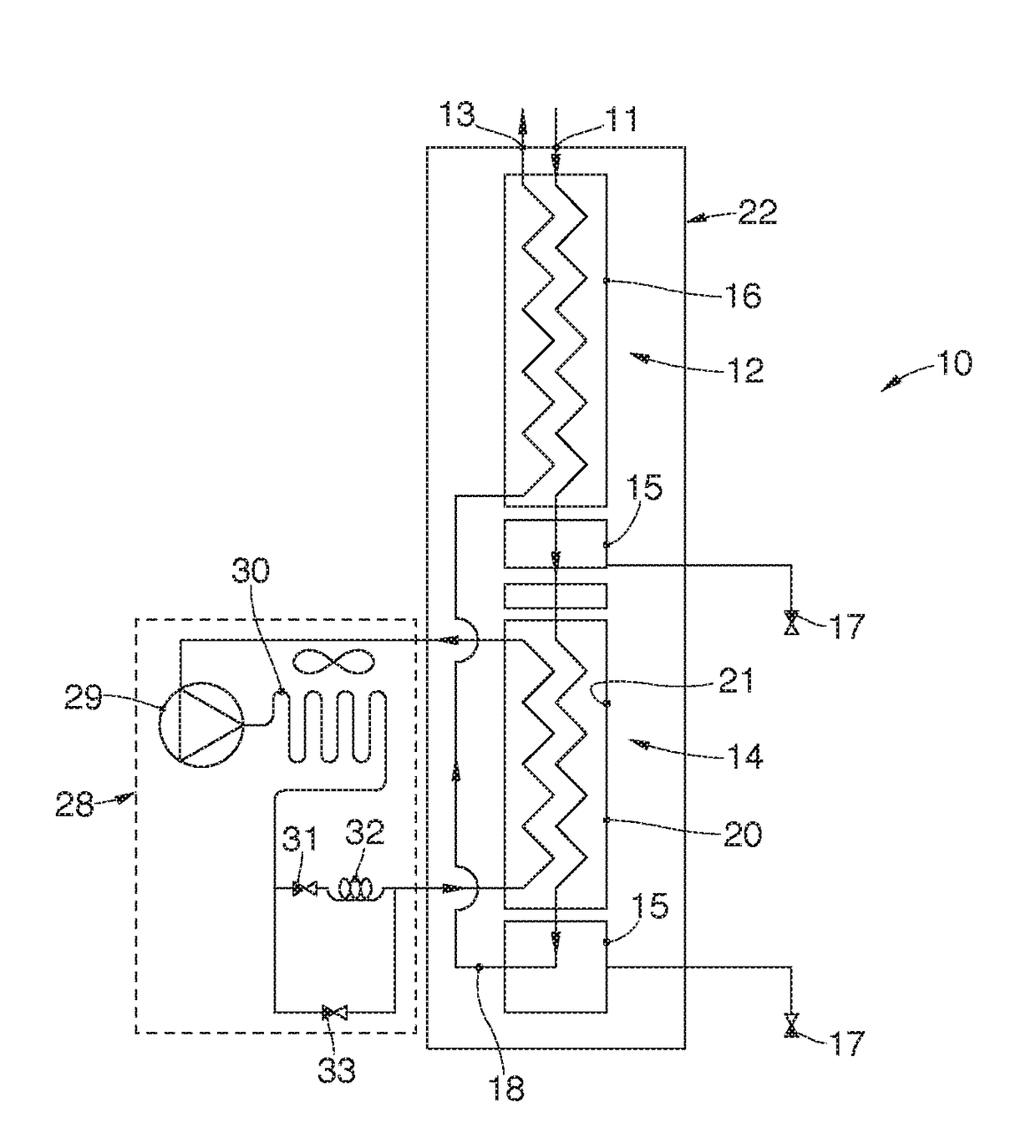
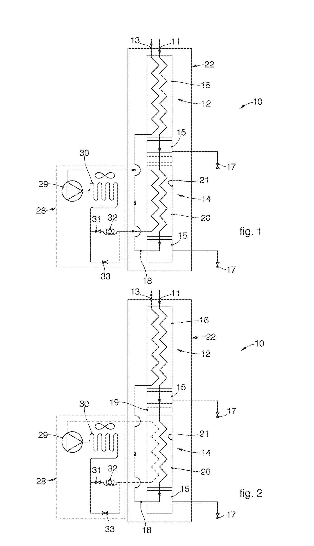
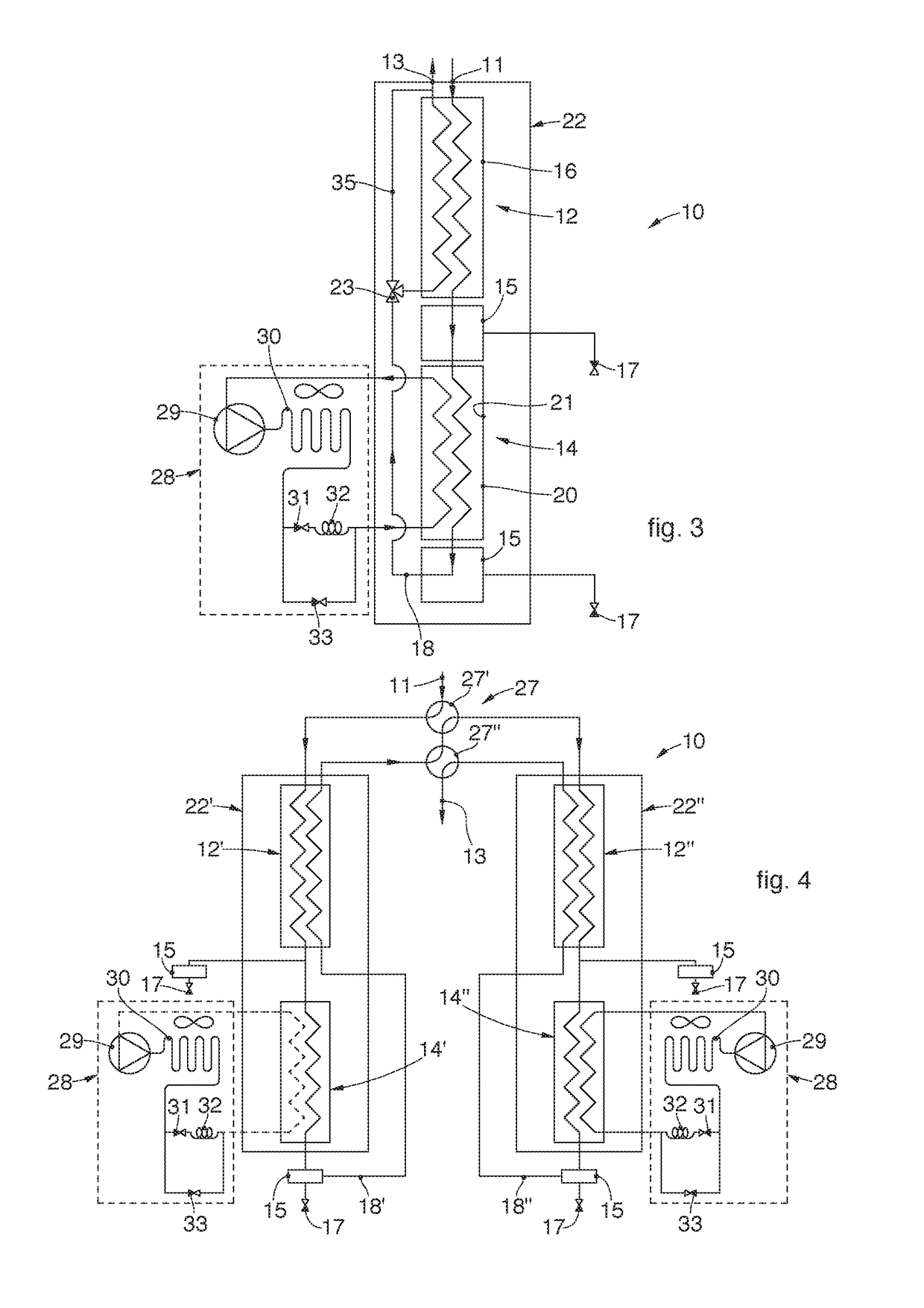
Dryer for compressed air including at least one cooling unit (28), able to cool a refrigerant fluid circulating in at least one drying unit (22), provided with an air inlet (11) and an air outlet (13) and also comprising at least one circuit (18) inside which air to be treated circulates from said air inlet (11) to said air outlet (13). The dryer for compressed air comprises, along the circuit (18), at least one cooling apparatus (12), configured to cool the compressed air to positive temperatures, a few degrees above zero and near to freezing temperature, and at least one freezing apparatus (14), disposed downstream of the cooling apparatus (12) and configured to cool the compressed air to abundantly negative values.

Description

FIELD OF THE INVENTION[0001]The present invention concerns a dryer for compressed air and the corresponding method, able to be used in applications in which dehumidified compressed air must be available, such as, by way of example, in the pharmaceutical, food or other industry.[0002]The present invention can also be applied to dry and remove humidity from technical gases, such as, for example, but not only, nitrogen, helium and others.[0003]In particular, the humidity can be removed by the progressive cooling of the compressed air so as to obtain an abundantly negative dew point temperature, corresponding to a very high degree of dehumidification.BACKGROUND OF THE INVENTION[0004]The need is known, in numerous sectors such as, for example, the pharmaceutical and food sectors, to have compressed air or technical gases too, with a high quality level, which, in general, cannot be obtained by directly using a stream of ambient air which has been previously compressed.[0005]It is therefor...

Claims


Application Information

Patent Timeline
IPC IPC(8): F24F3/14F25D21/12B01D53/26
CPCF24F3/1405F25D21/12B01D53/265B01D2256/10B01D2256/18
Inventor DE PIERO, PAOLOVEZIL, STEFANOCAPELLARI, GIOVANNI BATTISTA
Owner OFF MEC INDALI CON UNICO SOCIO
Learn More