
Water tower applied to the water source heat pump central air conditioner

Active Publication Date: 2017-03-16
GUANGDONG JINBEI ENERGY EFFICIENT TECH
View PDF7 Cites 20 Cited by
  • Summary
  • Abstract
  • Description
  • Claims
  • Application Information

AI Technical Summary

Benefits of technology

[0005]An aspect relates to an energy-saving and space-saving water tower applied to a water source heat pump central air conditioner, by which an air-conditioning system of a multi-storey building can be controlled storey by storey, and the energy consumption of the main control water pump can be reduced.
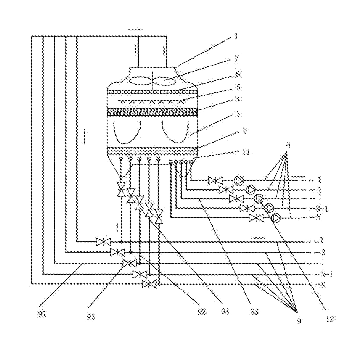
[0006]The water tower applied to the water source heat pump central air conditioner of embodiments of the present invention comprises a tower body, a water storage tank, an air distributing device, cooling fillers, a water distributing device, a water collector, and ventilating equipment, wherein the water storage tank is arranged at the bottom of the interior of the tower body; and the air distributing device, the cooling fillers, the water distributing device, the water collector and the ventilating equipment are sequentially arranged above the water storage tank; furthermore, the water tower applied to the water source heat pump central air conditioner comprises a plurality of return water pipes and a plurality of supply pipes; the water inlet ends of the multiple return water pipes are connected correspondingly with the return water outlets of a plurality of air conditioner main units that are arranged in all storeys, of the water source heat pump central air conditioner; and the water outlet ends of the multiple return water pipes are connected correspondingly with the top of the tower body through gate valves and with the water distributing device; water inlets of the multiple supply pipes are in connection with the water storage tank; and water outlets of the multiple supply pipes are in connection with water source inlets of the multiple air conditioner main units through small water pumps correspondingly. By the adoption of the above scheme, the water tower applied to the water source heat pump central air conditioner of embodiments of the present invention can control the air-conditioning system of the multi-storey building storey by storey, reduce the energy consumption of the main control water pump, and save the energy and space of the building.
[0007]Furthermore, the water tower applied to the water source heat pump central air conditioner comprises water temperature induction controllers which are electrically connected with the small water pumps; the water temperature induction controllers detect the temperature of the return water outlets of the multiple air conditioner main units, obtain a temperature signal through processing, and control the small water pumps corresponding to the multiple air conditioner main units correspondingly to operate according to the temperature signal. By the adoption of the water temperature induction controller, intelligent control over the small water pumps in all storeys can be achieved easily, and a response can be given in time according to the whether people are in all storeys or whether an operating is needed or not.

Problems solved by technology

The power of the existing water tower is huge, and energy consumption is extremely high.
Due to the fact that only the main control design of the return water main and the supply main is adopted for the structure of the existing water tower, the existing water tower is not suitable for controlling the multi-storey building storey by storey.
For example, in a public building such as an office building or a hotel, if workers of a certain department work overtime in a certain storey or if customers are only in some storey of a hotel, the existing water tower still has to operate around the clock, and consequentially severe waste can be caused.

Method used


Image

  • Water tower applied to the water source heat pump central air conditioner
  • Water tower applied to the water source heat pump central air conditioner

Examples


embodiment 1

[0019]FIG. 1 is the structural schematic diagram of the water tower applied to the water source heat pump central air conditioner of embodiments of the present invention. The water tower applied to the water source heat pump central air conditioner of embodiments of the present invention comprises a tower body 1, a water storage tank 2, an air distributing device 3, cooling fillers 4, a water distributing device 5, a water collector 6, ventilating equipment 7, a plurality of return water pipes 9 and a plurality of supply pipes 8. The water storage tank 2 is arranged at the bottom of the interior of the tower body 1, and the air distributing device 3, the cooling fillers 4, the water distributing device 5, the water collector 6 and the ventilating equipment 7 are arranged above the water storage tank 2 in sequence. The water inlet ends of the multiple return water pipes 9 are in connection with return water outlets of a plurality of air conditioner main units, arranged in all storeys...

embodiment 2

[0031]The structure of a water tower in the embodiment is similar to that of the water tower in embodiment I, with the difference being that the two two-way valves in each of the multiple return water pipes in embodiment I are replaced by a three-way valve; that is, the water tower in the embodiment is provided with multiple three-way valves which are installed in the multiple return water pipes 9 correspondingly. Each of the multiple return water pipes 9 is in connection with an inlet of the three-way valve in the return water pipe 9. One of the two pipelines of the return water pipe 9 is in connection with one outlet of the three-way valve, and the other pipeline is in connection with the other outlet of the three-way valve.

embodiment 3

[0032]The structure of a water tower of the embodiment is similar to that of the water tower in embodiment I, with the difference being that a plurality of electromagnetic valves used for controlling the water quantity are additionally arranged. The multiple electromagnetic valves are in connection with the multiple supply pipes 8 correspondingly.

[0033]Compared with the prior art, the water tower applied to the water source heat pump central air conditioner of embodiments of the present invention can control the air-conditioning system of the multi-storey building storey by storey; reduce the energy consumption of the main control water pump and save the energy the space of the building.

[0034]Although the present invention has been disclosed in the form of preferred embodiments and variations thereon, it will be understood that numerous additional modifications and variations could be made thereto without departing from the scope of the invention.

[0035]For the sake of clarity, it is...


PUM


Abstract

A water tower applied to the water source heat pump central air conditioner is provided, and includes a tower body, a water storage tank, an air distributing device, cooling fillers, a water distributing device, a water collector, and ventilating equipment, wherein the water storage tank is arranged at the bottom of the interior of the tower body, and the air distributing device, the cooling fillers, the water distributing device, the water collector and the ventilating equipment are sequentially arranged above the water storage tank. Furthermore, the water tower applied to the water source heat pump central air conditioner includes a plurality of return water pipes and a plurality of supply pipes; the water inlet ends of the multiple return water pipes are in connection with the return water outlets of a plurality of air conditioner main units, arranged in all storeys correspondingly.

Description

CROSS-REFERENCE TO RELATED APPLICATIONS[0001]This application claims priority to PCT Application No. PCT / CN2014 / 092174, having a filing date of Nov. 25, 2014, based off of Chinese application No. 201410085833.2 having a filing date of Mar. 10, 2014, the entire contents of which are hereby incorporated by reference.FIELD OF TECHNOLOGY[0002]The following relates to the field of air conditioner, in particular to a water tower applied to the water source heat pump central air conditioner.BACKGROUND[0003]A water source heat pump central air conditioner is a low-carbon and energy-saving air conditioner that has been developed in recent years, with the most important character being that the powerful air-exhausting and heat-dissipating refrigeration of an externally-suspended air conditioner is transformed into a built-in central water cooling system.[0004]An existing water tower of a water source heat pump central air conditioner generally comprises a tower body, a water storage tank, an ...

Claims


Application Information

Patent Timeline
IPC IPC(8): F24F3/00F25B13/00
CPCF25B13/00F24F3/001F24F3/06F28C1/00F28F25/00F28F27/003F28F27/02Y02B30/70
Inventor QIAN, TUQIAN, XIAOPENG
Owner GUANGDONG JINBEI ENERGY EFFICIENT TECH
Learn More