
Electronic system, as well as manufacturing method, and device for manufacturing an electronic system

Inactive Publication Date: 2017-03-16
ROBERT BOSCH GMBH
View PDF7 Cites 0 Cited by
  • Summary
  • Abstract
  • Description
  • Claims
  • Application Information

AI Technical Summary

Benefits of technology

The patent is about a design for electronic components that can be installed in a compact way on a printed circuit board, by stacking them in a molded housing. This helps to save space on the board and reduces the chances of interference between components. The patent also explains a manufacturing process that can rapidly and efficiently implement this design. Overall, this design allows for the efficient use of space and better performance of the components.

Problems solved by technology

A significant challenge arises when radio chips are installed in a stack.
The components, which are placed over the radio chip, can degrade the proper functioning thereof.
Such degradations can even prevent the radio chip from functioning in a specified range, thus, for example, induce a change in the output or even result in a shifting of the transmit and receive frequencies.
The result can be that the radio chip is no longer able to communicate with other devices.

Method used


Image

  • Electronic system, as well as manufacturing method, and device for manufacturing an electronic system
  • Electronic system, as well as manufacturing method, and device for manufacturing an electronic system
  • Electronic system, as well as manufacturing method, and device for manufacturing an electronic system

Examples


Embodiment Construction

[0044]The following description of advantageous exemplary embodiments of the present invention employs the same or similar reference numerals for the elements that are shown in the various figures and whose function is similar, there being no need to repeat the description of these elements.

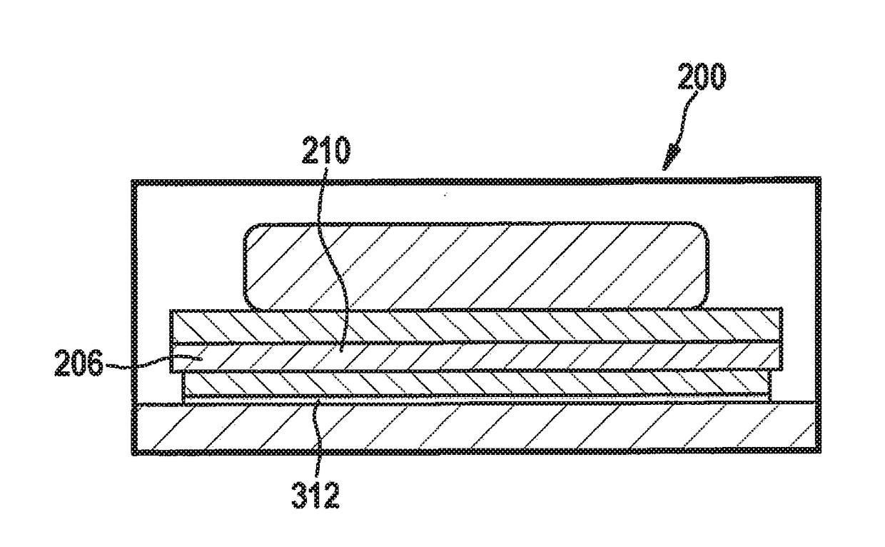
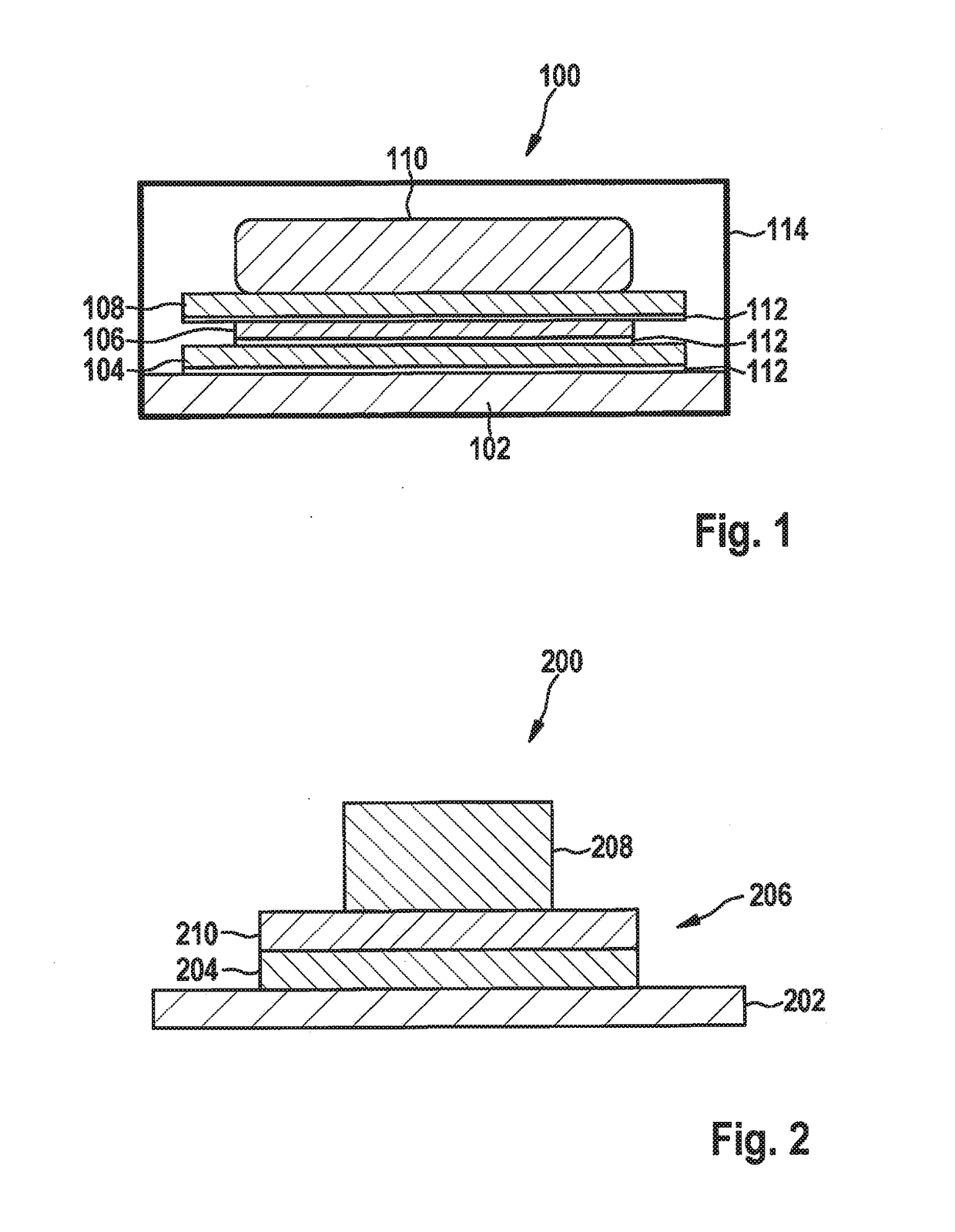
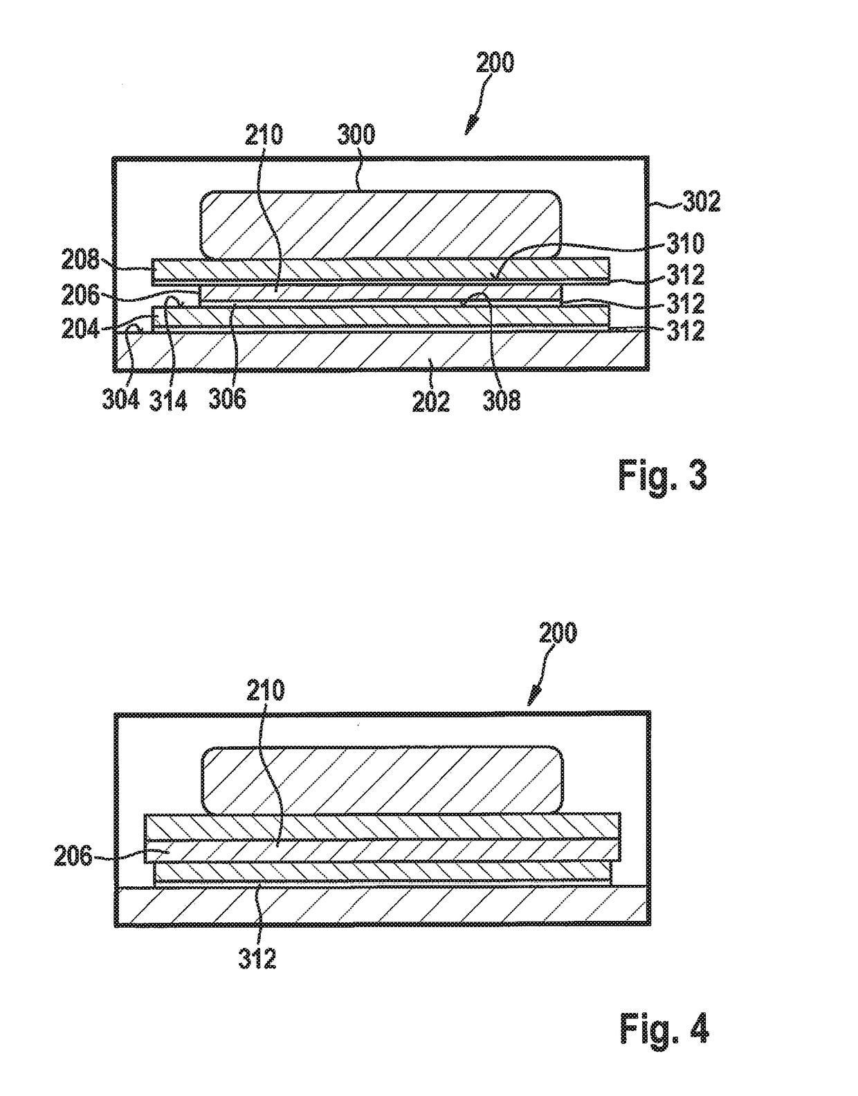
[0045]FIG. 1 shows a schematic representation of an electronic system 100 having a radio chip in accordance with the related art. Electronic system 100 is provided as a stacked configuration of a substrate, respectively carrier 102, a radio chip 104 having a thickness of 100 μm, a spacer element, respectively spacer chip 106 of silicon having a thickness of 75 μm, a microcontroller 108 having a thickness of 100 μm and a sensor, respectively sensor packet 110. A chip adhesive 112 having a nominal thickness of 20 μm fixes radio chip 104 to substrate 102, spacer chip 106 to radio chip 104, and microcontroller 108 to spacer chip 106. Electronic system 100 also has a housing 114 in the form of a molde...


PUM

PropertyMeasurementUnit
Thicknessaaaaaaaaaa
Thicknessaaaaaaaaaa
Permittivityaaaaaaaaaa

Abstract

An electronic system having a carrier, at least one radio chip mounted on the carrier, a spacer element, which is mounted on the radio chip and features a material having a predefined permittivity number, and at least one electronic component mounted on the radio chip.

Description

FIELD OF THE INVENTION[0001]The present invention relates to an electronic system, to a method for manufacturing an electronic system, to a device for manufacturing an electronic system, as well as to a corresponding computer program product.BACKGROUND INFORMATION[0002]It is believed that many IC chips, that is, semiconductor substrates having electronic circuits disposed thereon, are individually bonded and molded in a housing. There have always been molded housings that contain two or more chips. This holds for acceleration sensors, rotation-rate sensors and combination sensors, for example. Increasing miniaturization and higher levels of integration require that ever more chips, for example, two MEMS chips, three ASICs, and one microcontroller be installed in one housing. In keeping with developments in the “Internet of Things” sector, the next integration step is to combine MEMS sensors with microcontrollers and a radio chip in a highly integrated molded housing (for example, BG...

Claims


Application Information

Patent Timeline
IPC IPC(8): B81B7/00G06F17/50B81C1/00
CPCB81B7/0074G06F2217/40G06F17/5072B81C1/00333H01L23/66H01L25/0657H01L2224/32145H01L2224/32225G06F30/392G06F2113/18
Inventor KAACK, ROLFBRUENDEL, MATHIASHAAS, LISA MARIE
Owner ROBERT BOSCH GMBH
Learn More