Image display apparatus
a technology of image display and display apparatus, which is applied in the direction of static indicating devices, instruments, cathode-ray tube indicators, etc., can solve the problems of increased display apparatus may not be used, etc., and achieves the effect of increasing the power consumption of image display apparatus and intensifying eye fatigue of users
- Summary
- Abstract
- Description
- Claims
- Application Information
AI Technical Summary
Benefits of technology
Problems solved by technology
Method used
Image
Examples
example 1
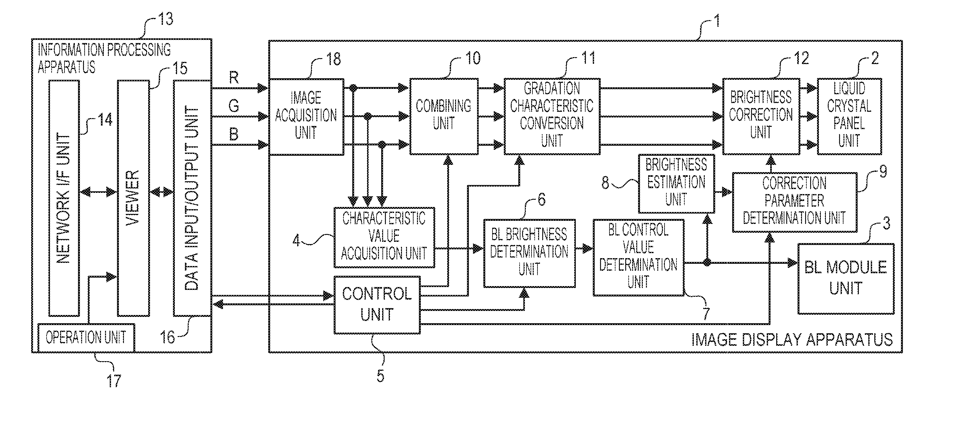
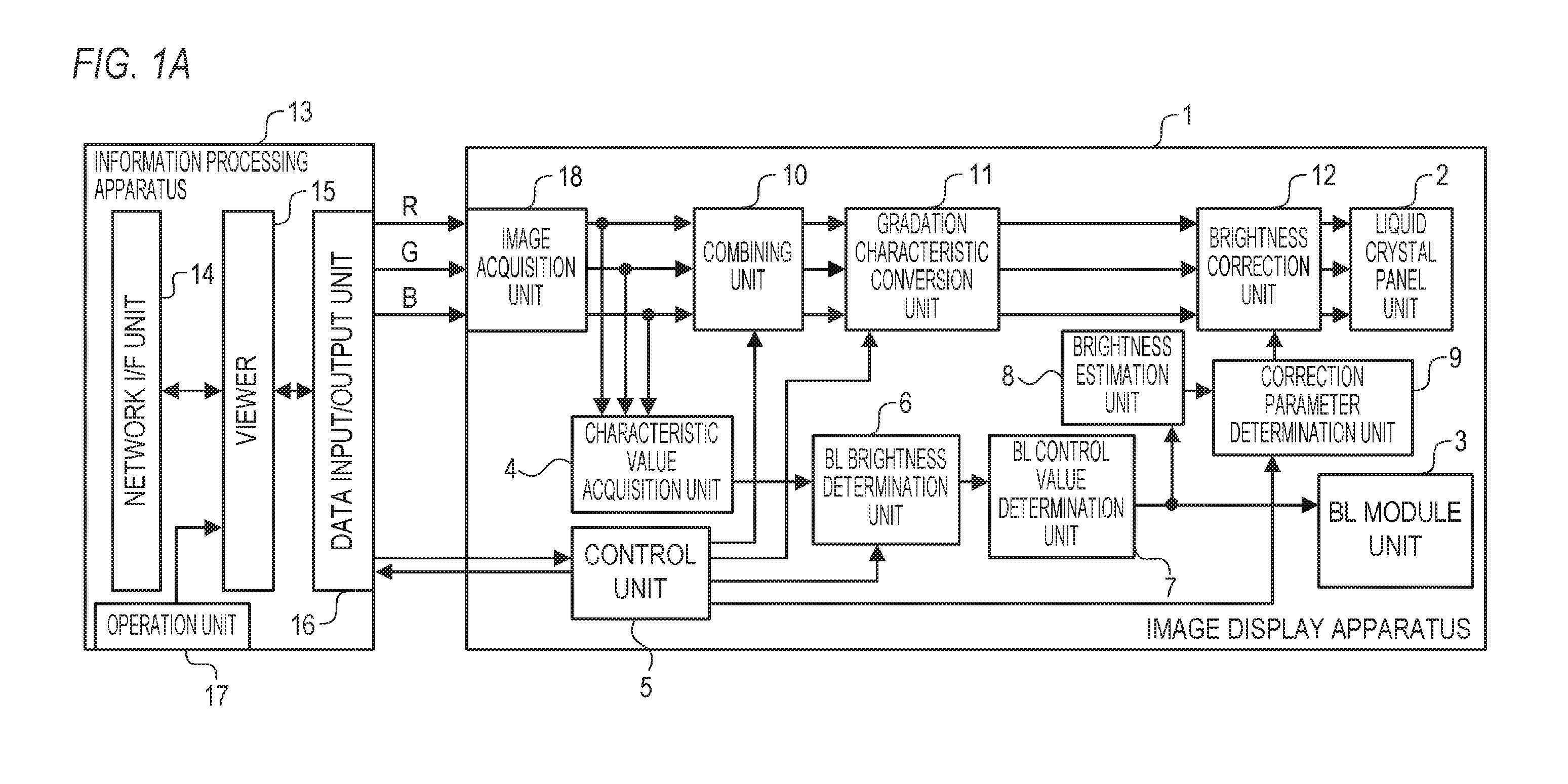
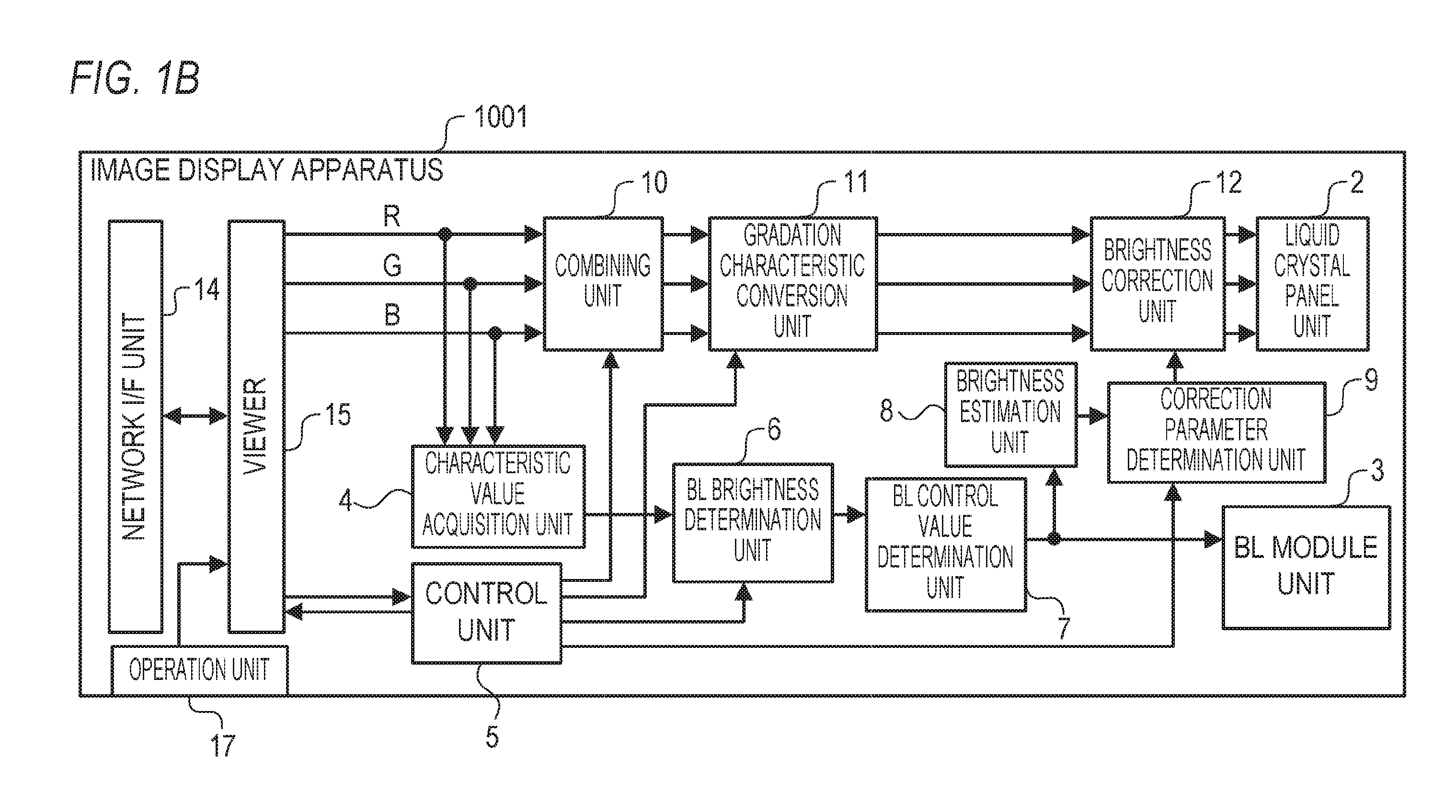
[0075]An image display apparatus according to Example 1 of the present invention will now be described. Description of a case where the image display apparatus according to this example is a transmission type liquid crystal display apparatus follows, but the image display apparatus according to this example is not limited to the transmission type liquid crystal display apparatus. The image display apparatus according to this example can be any image display apparatus constituted by a light-emitting unit and a display unit configured to display an image on a screen by modulating the light from the light-emitting unit based on the image data. For example, the image display apparatus according to this example may be a reflection type liquid crystal display apparatus. The image display apparatus according to this example may be a micro electro mechanical system (MEMS) shutter type display apparatus that uses MEMS shutters instead of liquid crystal elements.
[0076]The light-emitting unit ...
example 2
[0128]An image display apparatus according to Example 2 of the present invention will now be described. In the following, the configuration and processing that are different from Example 1 will be described in detail, and description of the configuration and processing that are the same as Example 1 will be omitted.
[0129]In Example 1, the emission brightness of each light-emitting area may become considerably different among the divided areas. For example, the emission brightness of each light-emitting area may become considerably different between an HDR divided area and a non-HDR divided area. This major difference causes the generation of a halo, the generation of flickering in a moving image display, and the like. Therefore in this example, spatial low-pass filter processing (spatial LPF processing: smoothing processing) is performed to smooth the distribution of the emission brightness of a plurality of light-emitting areas.
[0130]FIGS. 8A and 8B are block diagrams depicting exa...
example 3
[0143]An image display apparatus according to Example 3 of the present invention will now be described. In the following, the configuration and processing that are different from Example 1 will be described in detail, and description on the configuration and processing that are the same as Example 1 will be omitted. An example in a case where a characteristic configuration of this example is applied to the configuration of Example 1 will be described below, but the characteristic configuration of this example is applicable to the configuration of Example 2 as well.
[0144]In Examples 1 and 2, information on the areas on the screen, where the HDR display is performed, are notified to the user. However, the light from each light-emitting area diffuses around the area. Therefore in a peripheral area around the area where the HDR display is performed, the irradiation brightness may be controlled to the brightness far higher than the irradiation brightness in the case of not performing the...
PUM
 Abstract
Description
Claims
Application Information
 - R&D
- Intellectual Property
- Life Sciences
- Materials
- Tech Scout
- Unparalleled Data Quality
- Higher Quality Content
- 60% Fewer Hallucinations
Browse by: Latest US Patents, China's latest patents, Technical Efficacy Thesaurus, Application Domain, Technology Topic, Popular Technical Reports.
© 2025 PatSnap. All rights reserved.Legal|Privacy policy|Modern Slavery Act Transparency Statement|Sitemap|About US| Contact US: help@patsnap.com


