
Control apparatus for internal combustion engine, and control method for internal combustion engine

a control apparatus and internal combustion engine technology, applied in the direction of electric control, fuel injection control, machines/engines, etc., can solve the problem of increasing unable to appropriately control the amount of fuel injection from the second injection valve, and difficult to detect a change in the determination parameter for determining whether the degree of inter-cylinder imbalance in the amount of fuel supplied into each cylinder is large, etc. problem, to achieve the effect of accurate diagnosis

Inactive Publication Date: 2017-02-23
TOYOTA JIDOSHA KK
View PDF1 Cites 1 Cited by
  • Summary
  • Abstract
  • Description
  • Claims
  • Application Information

AI Technical Summary

Benefits of technology

The patent describes a control system for an internal combustion engine that can diagnose if there is a malfunction in fuel injection from one of the engine's injection valves without affecting the performance of the other valve. The system reduces the fuel injection amount from the malfunctioning valve and increases the injection amount from the other valve to accurately diagnose the malfunction. This allows for timely maintenance and replacement of the malfunctioning valve, ensuring optimal engine performance.

Problems solved by technology

Incidentally, when there is a malfunction in at least one of fuel injection from the first injection valve and fuel injection from the second injection valve, the degree of inter-cylinder imbalance in the amount of fuel supplied into each cylinder increases.
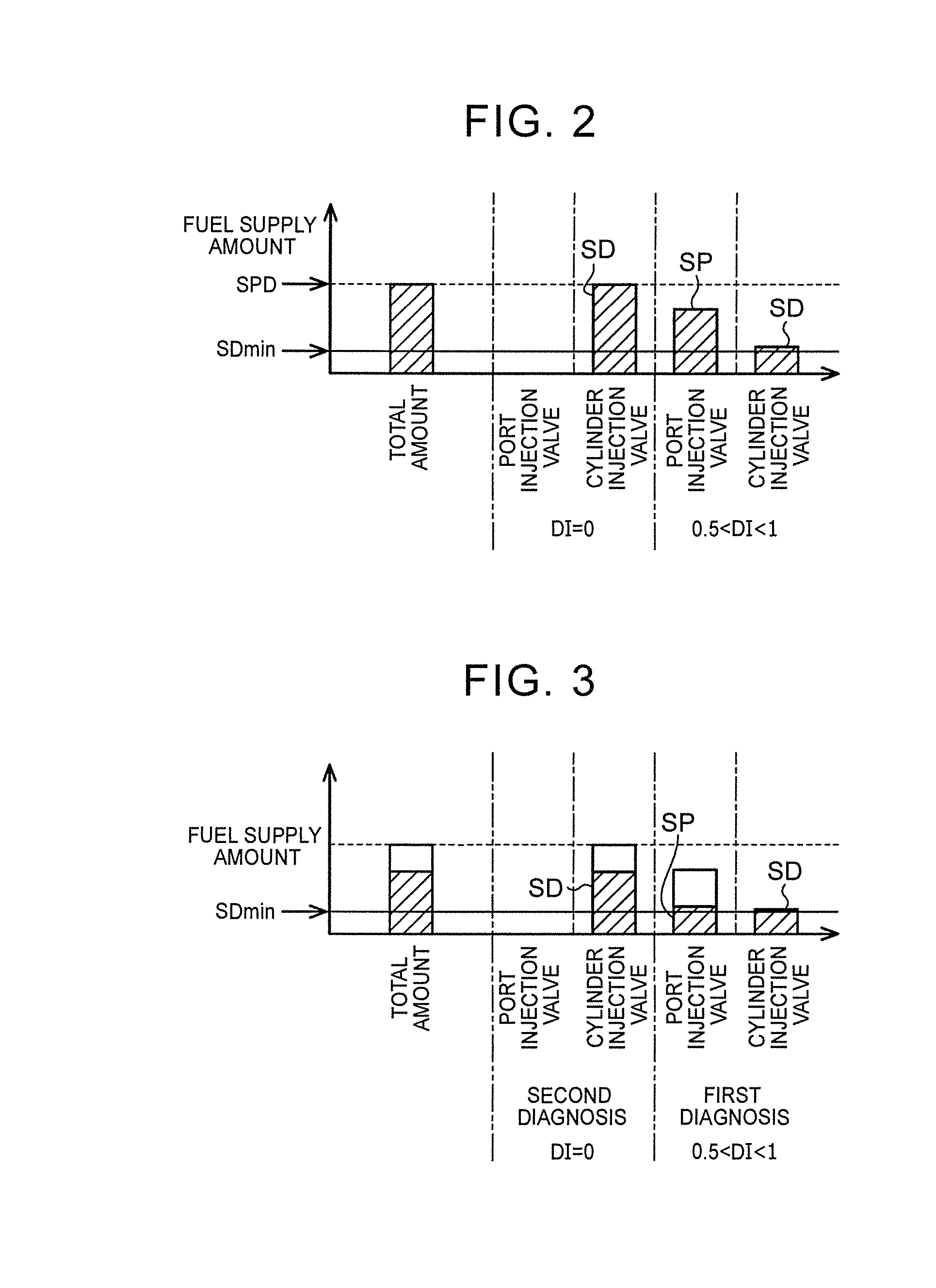
When the required fuel injection amount from the second injection valve is reduced in this way, the required fuel injection amount may become smaller than a minimum injection amount Fmin in terms of the performance of the second injection valve, so it may not be possible to appropriately control the fuel injection amount from the second injection valve.
As a result, it becomes difficult to detect a change in determination parameter for determining whether the degree of inter-cylinder imbalance in the amount of fuel supplied into each cylinder is large.

Method used


Image

  • Control apparatus for internal combustion engine, and control method for internal combustion engine
  • Control apparatus for internal combustion engine, and control method for internal combustion engine
  • Control apparatus for internal combustion engine, and control method for internal combustion engine

Examples


Embodiment Construction

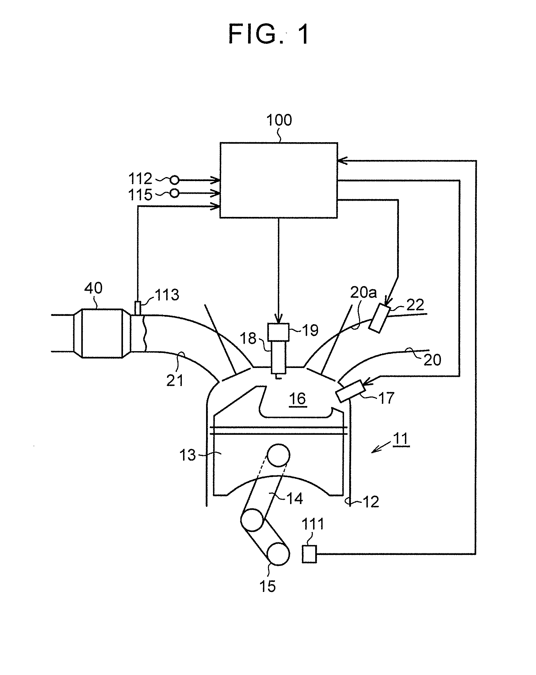
[0027]Hereinafter, an example embodiment of the control apparatus for an internal combustion engine will be described with reference to FIG. 1 to FIG. 5. FIG. 1 shows an electronic control unit 100 that is the control apparatus for an internal combustion engine according to the present embodiment and an internal combustion engine 11 that is controlled by the electronic control unit 100. As shown in FIG. 1, the internal combustion engine 11 is a multi-cylinder internal combustion engine having a plurality of cylinders 12. A piston 13 is provided in each cylinder 12. These pistons 13 are coupled to a crankshaft 15 via connecting rods 14. The crankshaft 15 is an output shaft of the internal combustion engine 11. The reciprocating motion of each piston 13 is converted to the rotational motion of the crankshaft 15 by a corresponding one of the connecting rods 14. The rotation speed of the crankshaft 15 is detected by a crank position sensor 111.

[0028]An upward space on the piston 13 with...


PUM


Abstract

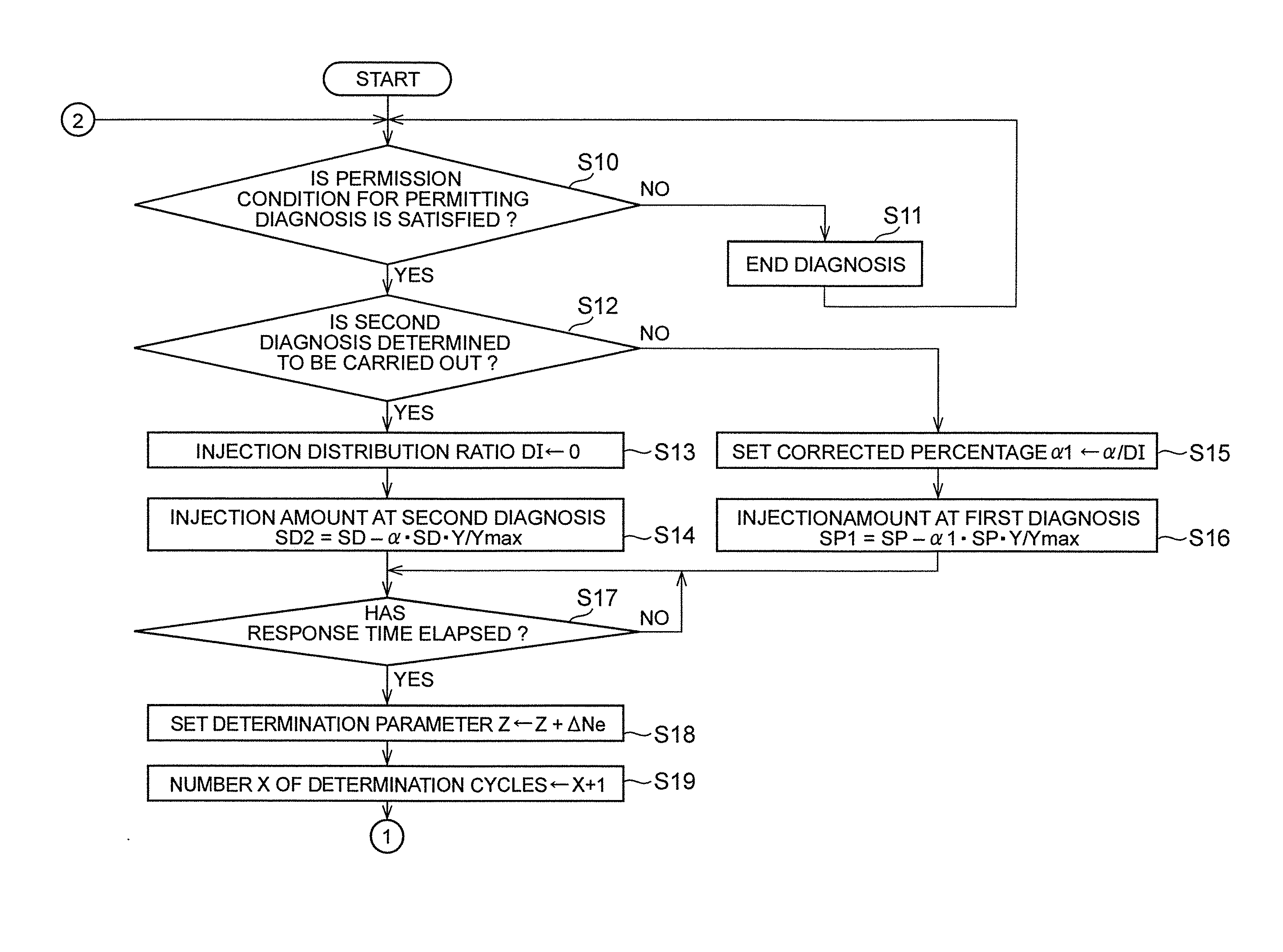
A control apparatus includes an electronic control unit configured to: carry out a first diagnosis and a second diagnosis; control a first injection valve and a second injection valve such that fuel is injected from both the first injection valve and the second injection valve, and such that a fuel injection amount from the second injection valve is not reduced and a fuel injection amount from the first injection valve is reduced, when carrying out the first diagnosis; and control the first injection valve such that fuel is not injected from the first injection valve, and control the second injection valve such that the fuel injection amount from the second injection valve is reduced in a state where fuel is injected from the second injection valve, when carrying out the second diagnosis.

Description

CROSS-REFERENCE TO RELATED APPLICATIONS[0001]This application claims priority to Japanese Patent Application No.[0002]2015-160573 filed on Aug. 17, 2015 and to Japanese Patent Application No. 2016-088180 filed on Apr. 26, 2016, the entire contents of which are hereby incorporated by reference.BACKGROUND 1. Technical Field[0003]The disclosure relates to a control apparatus for an internal combustion engine and a control method for an internal combustion engine, which are applied to a multi-cylinder internal combustion engine in which a first injection valve and a second injection valve are provided for each cylinder.[0004]2. Description of Related Art[0005]Japanese Patent Application Publication No. 2014-190243 (JP 20141 90243 A) describes a multi-cylinder internal combustion engine in which a first injection valve and a second injection valve are provided for each cylinder. Each first injection valve injects fuel into an intake passage. Each second injection valve injects fuel into ...

Claims


Application Information

Patent Timeline
Patent Type & Authority Applications(United States)
IPC IPC(8): F02D41/00F02D41/22F02D41/30
CPCF02D41/0085F02D41/3094F02D2200/06F02D2041/224F02D41/22F02D41/221
Inventor TSURUOKA, KAZUKI
Owner TOYOTA JIDOSHA KK
Learn More