
Distance measurement device, distance measurement method, and distance measurement program

a technology of distance measurement and distance measurement method, which is applied in the direction of distance measurement, instruments, television systems, etc., can solve the problems of difficult to efficiently perform imaging and distance measurement, and achieve the effect of efficiently performing imaging and distance measuremen

Active Publication Date: 2017-02-16
FUJIFILM CORP
View PDF6 Cites 9 Cited by
  • Summary
  • Abstract
  • Description
  • Claims
  • Application Information

AI Technical Summary

Benefits of technology

The patent proposes a device, method, and program for measuring distance efficiently by overlapping the imaging and distance measurement periods. This results in faster and more effective use of the device's resources.

Problems solved by technology

However, in the above-described distance measurement and imaging device, since imaging is performed regardless of the distance measurement, it is difficult to efficiently perform imaging and the distance measurement.

Method used


Image

  • Distance measurement device, distance measurement method, and distance measurement program
  • Distance measurement device, distance measurement method, and distance measurement program
  • Distance measurement device, distance measurement method, and distance measurement program

Examples


Embodiment Construction

[0051]Hereinafter, an example of an embodiment of a distance measurement device according to the technique of the present disclosure will be described referring to the accompanying drawings. In this embodiment, a “distance measurement” indicates a measurement of a distance to a subject to be a measurement target. In this embodiment, the magnitude of exposure has the same meaning as the level of exposure.

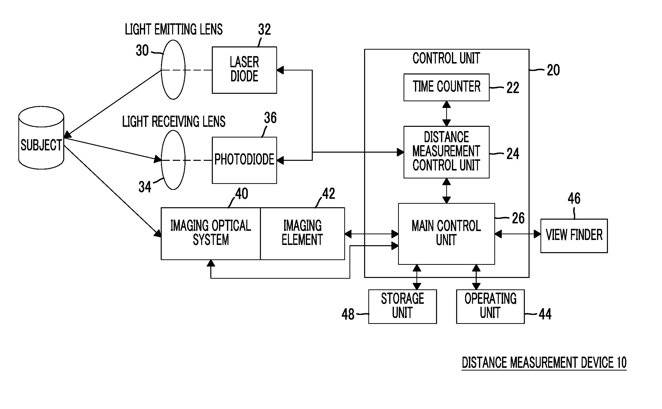
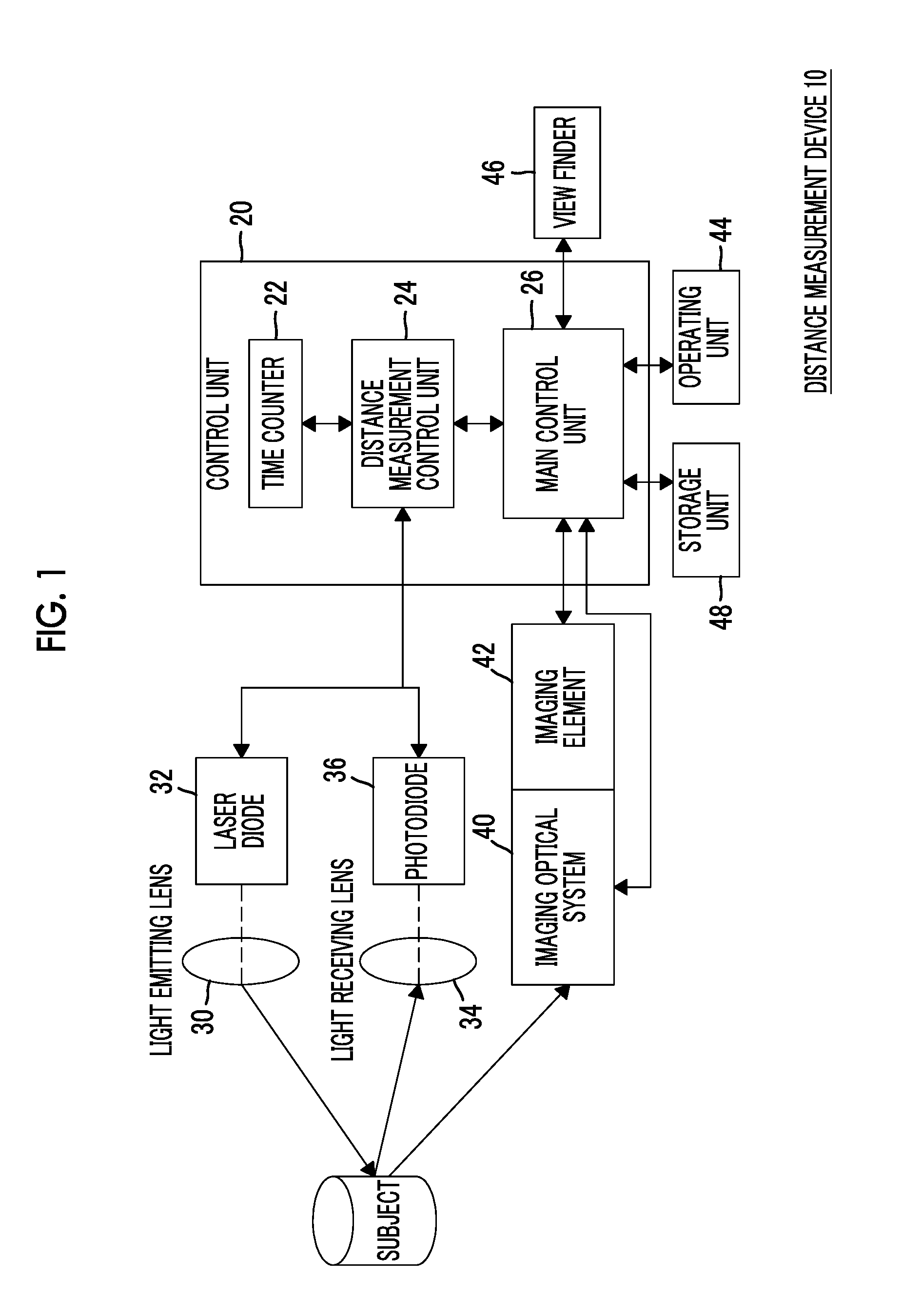
[0052]First, the configuration of the distance measurement device according to this embodiment will be described. FIG. 1 is a block diagram showing the configuration of a main part of a distance measurement device 10 according to this embodiment.

[0053]The distance measurement device 10 of this embodiment has a function of performing a distance measurement and a function of imaging a subject to generate a captured image indicating the subject. The distance measurement device 10 of this embodiment comprises a control unit 20, a light emitting lens 30, a laser diode 32, a light receivin...


PUM


Abstract

A distance measurement device includes an imaging unit which captures a subject image formed by an imaging optical system forming the subject image indicating a subject, an emission unit which emits directional light as light having directivity along an optical axis direction of the imaging optical system, a light receiving unit which receives reflected light of directional light from the subject, a derivation unit which derives a distance to the subject based on a timing at which directional light is emitted by the emission unit and a timing at which reflected light is received by the light receiving unit, and a control unit which performs control such that at least a part of an imaging period by the imaging unit overlaps at least a part of a distance measurement period by the emission unit, the light receiving unit, and the derivation unit.

Description

CROSS-REFERENCE TO RELATED APPLICATIONS[0001]This application is a continuation application of International Application No. PCT / JP2015 / 056876, filed Mar. 9, 2015, the disclosure of which is incorporated herein by reference in its entirety. Further, this application claims priority from Japanese Patent Application No. 2014-095557, filed May 2, 2014, and Japanese Patent Application No. 2014-159803, filed Aug. 5, 2014, the disclosures of which are incorporated herein by reference in their entireties.BACKGROUND[0002]1. Technical Field[0003]A technique of the present disclosure relates to a distance measurement device, a distance measurement method, and a distance measurement program.[0004]2. Related Art[0005]JP2008-96181A discloses a device including time detection means for detecting the time from the emission of measurement light to the reception of measurement light by light receiving means, shake amount detection means for detecting a shake amount of a housing during emission of me...

Claims


Application Information

Patent Timeline
Patent Type & Authority Applications(United States)
IPC IPC(8): G01S17/08H04N5/238H04N5/235G02B7/40H04N5/232G01S17/10H04N23/75
CPCG01S17/08G02B7/40H04N5/238H04N5/2353H04N5/23293G01C3/06G01S17/10G01S17/88G01S7/484G01S7/4876H04N23/673H04N23/633H04N23/73H04N23/75
Inventor MASUDA, TOMONORITAMAYAMA, HIROSHI
Owner FUJIFILM CORP
Learn More