Failure cause diagnostic device for injection molding machine
- Summary
- Abstract
- Description
- Claims
- Application Information
AI Technical Summary
Benefits of technology
Problems solved by technology
Method used
Image
Examples
embodiment
2. Embodiment
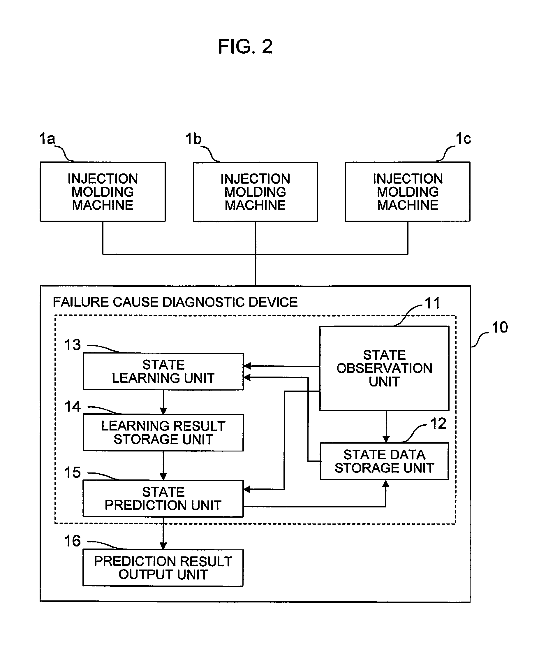
[0036]FIG. 2 is a diagram showing a schematic configuration of the failure cause diagnostic device according to the one embodiment of the present invention. A failure cause diagnostic device 10 of the present embodiment comprises a supervised machine learning device (surrounded by a dotted-line frame in FIG. 2). The failure cause diagnostic device 10 is connected to a plurality of injection molding machine 1a, 1b and 1c by communication lines, signal lines, or the like. State data indicative of the respective states of the injection molding machines 1a to 1c are transmitted from the injection molding machines to the failure cause diagnostic device 10.
[0037]A state observation unit 11 of the failure cause diagnostic device 10 is a function means for observing the state data for injection molding delivered from the injection molding machines 1a to 1c and acquiring them into the failure cause diagnostic device 10. The state data include, for example, a load on a driving un...
PUM
| Property | Measurement | Unit |
|---|---|---|
| pressure | aaaaa | aaaaa |
| clamping force | aaaaa | aaaaa |
| failure spectrum | aaaaa | aaaaa |
Abstract
Description
Claims
Application Information
 - R&D
- Intellectual Property
- Life Sciences
- Materials
- Tech Scout
- Unparalleled Data Quality
- Higher Quality Content
- 60% Fewer Hallucinations
Browse by: Latest US Patents, China's latest patents, Technical Efficacy Thesaurus, Application Domain, Technology Topic, Popular Technical Reports.
© 2025 PatSnap. All rights reserved.Legal|Privacy policy|Modern Slavery Act Transparency Statement|Sitemap|About US| Contact US: help@patsnap.com


