Blade set, hair cutting appliance,and related manufacturing method

Active Publication Date: 2017-02-02
KONINKLJIJKE PHILIPS NV
View PDF3 Cites 5 Cited by
  • Summary
  • Abstract
  • Description
  • Claims
  • Application Information

AI Technical Summary

Benefits of technology

The present patent aims to provide an alternative blade set that can be used for both shaving and trimming. The blade set should provide a comfortable user experience and improve operating performance while reducing the time required for cutting. The manufacturing method should be cost-efficient and minimalize the number of components used. The technical effects of the present invention include providing a more versatile and efficient blade set for shaving and trimming.

Problems solved by technology

Common electric razors are not particularly suited for cutting hair to a desired variable length above the skin, i.e., for precise trimming operations.
But even if they did, e.g. by adding attachment spacer parts, such as spacing combs, the configuration of the foil, which typically involves a large number of small perforations, would diminish the efficient capture of all but the shortest and stiffest of hairs.
Similarly, common hair trimmers are not particularly suited for shaving, primarily because the separate cutter blades require a certain rigidity, and therefore thickness, to perform the scissor action without deforming.
Furthermore, combined shaving and trimming devices show several drawbacks since they basically require two cutting blade sets and respective drive mechanisms.
Consequently, these devices are heavier and more susceptible to wear than standard type single-purpose hair cutting appliances, and also require costly manufacturing and assembling processes.
Similarly, operating these combined devices is often experienced to be rather uncomfortable and complex.
Even in case a conventional combined shaving and trimming device comprising two separate cutting sections is utilized, handling the device and switching between different operation modes may be considered as being time-consuming and not very user-friendly.

Method used


Image

  • Blade set, hair cutting appliance,and related manufacturing method
  • Blade set, hair cutting appliance,and related manufacturing method
  • Blade set, hair cutting appliance,and related manufacturing method

Examples


Embodiment Construction

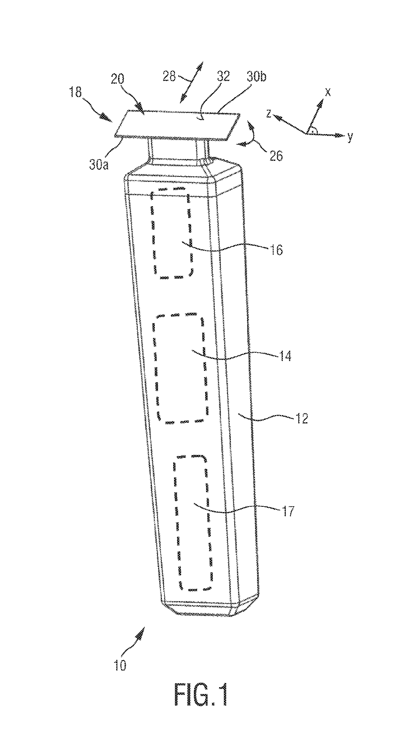
[0090]FIG. 1 schematically illustrates, in a simplified perspective view, an exemplary embodiment of a hair cutting appliance 10, particularly an electric hair cutting appliance 10. The cutting appliance 10 may comprise a housing 12, a motor indicated by a dashed block 14 in the housing 12, and a drive mechanism or drivetrain indicated by a dashed block 16 in a housing 12. For powering the motor 14, at least in some embodiments of the cutting appliance 10, an electrical battery, indicated by a dashed block 17 in the housing 12, may be provided, such as, for instance, a rechargeable battery, a replaceable battery, etc. However, in some embodiments, the cutting appliance 10 may be further provided with a power cable for connecting a power supply. A power supply connector may be provided in addition or in the alternative to the (internal) electric battery 17.

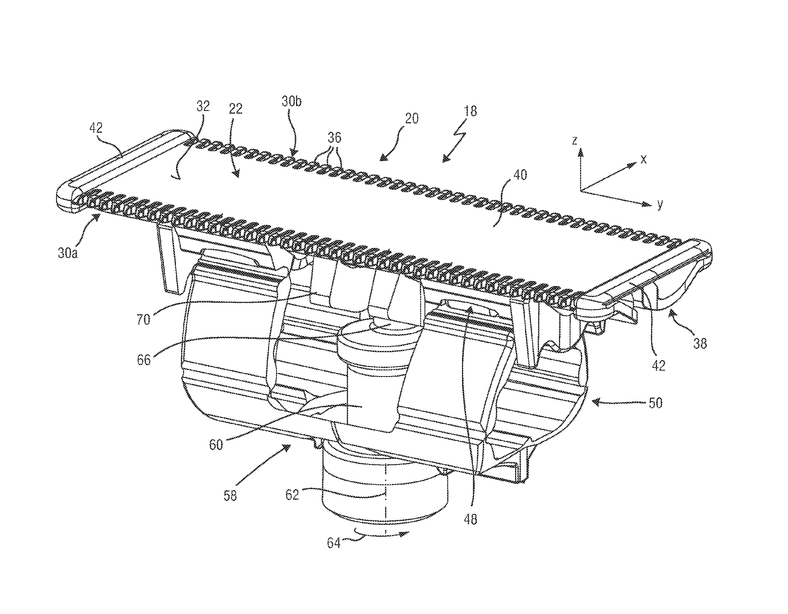
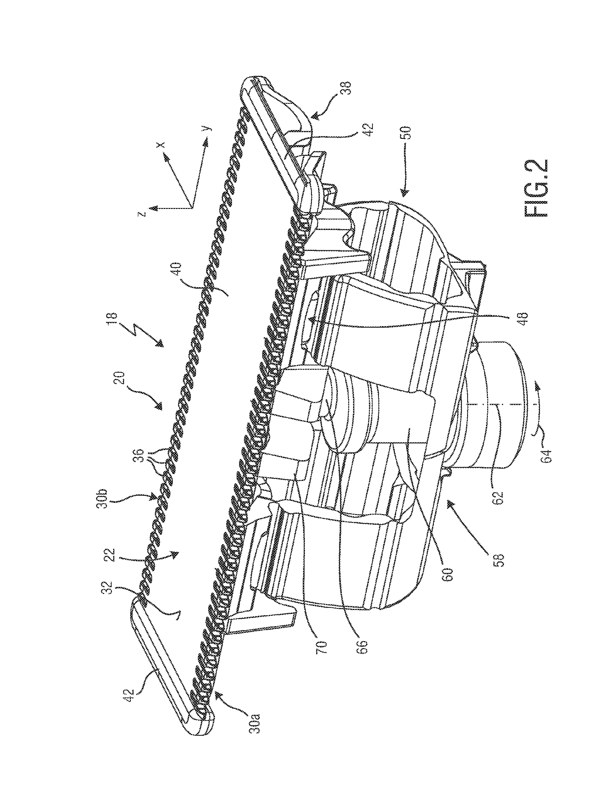
[0091]The cutting appliance 10 may further comprise a cutting head 18. At the cutting head 18, a blade set 20 may be attached to ...


PUM


Abstract

The present invention relates to a hair cutting appliance (10) and to a blade set (20) for a hair cutting appliance (10). Said blade set (20) comprises a stationary blade (22) comprising a first wall portion (100) and a second wall portion (102) that define therebetween a guide slot (96), a movable cutter blade (24) received at the guide slot (96), and a transmitting member (70) configured to be engaged by a driving member, wherein the transmitting member (70) is further configured to actuate the movable cutter blade (24) relative to the stationary blade (22), wherein the movable cutter blade (24) is laterally inserted into the guide slot (96), wherein the transmitting member (70) is fed to the stationary blade (22) in a feed direction (190) that is different from an insertion direction (188) of the movable cutter blade (24), and wherein the transmitting member (70) is coupled to the movable cutter blade (24), particularly to a main portion (78) thereof, such that the movable cutter blade (24) is secured at the stationary blade (22), particularly undetachably retained. The disclosure further relates to a method for manufacturing a respective blade (22).

Description

FIELD OF THE INVENTION[0001]The present disclosure relates to a hair cutting appliance, particularly to an electrically operated hair cutting appliance, and more particularly to a blade set for such an appliance. The blade set may be arranged to be moved through hair in a moving direction to cut hair. The blade set may comprise a stationary blade composed of a first wall portion and a second wall portion that define therebetween a guide slot, where a movable cutter blade may be at least partially encompassed and guided. The movable cutter may be actuated with respect to the stationary blade to cut hair. The present disclosure further relates to a method for manufacturing a blade set for a hair cutting appliance.BACKGROUND OF THE INVENTION[0002]WO 2013 / 150412 A1 discloses a hair cutting appliance and a corresponding blade set of a hair cutting appliance. The blade set comprises a stationary blade and a movable blade, wherein the movable blade can be reciprocatingly driven with respec...

Claims


Application Information

Patent Timeline
IPC IPC(8): B26B19/38
CPCB26B19/3893B26B19/3846B26B19/042
Inventor SABLATSCHAN, SIEGFRIED
Owner KONINKLJIJKE PHILIPS NV
Why Eureka
Try Eureka