
Balanced vanes and integrated actuation system for a variable geometry turbocharger

Active Publication Date: 2017-01-12
KANGYUE TECH
View PDF1 Cites 6 Cited by
  • Summary
  • Abstract
  • Description
  • Claims
  • Application Information

AI Technical Summary

Benefits of technology

The present patent describes a variable geometry turbine (VGT) for turbochargers of turbochargers. It includes a turbine nozzle with multiple vanes, each vane having an airfoil with an inner and outer disc. The nozzle plates have pockets to receive the inner and outer discs, respectively. An actuation system rotates the vanes to change the nozzle geometry. The actuation system employs a single acting hydraulic servo driven by a proportional solenoid. The servo has a spool and a piston that move the vane system in the turbine nozzle. This technology allows for precise control of the nozzle geometry for improved performance of turbochargers.

Problems solved by technology

For example increased turbocharger cost, decreased reliability, reduced durability, additional noise, more difficult packaging of the turbocharger in the engine compartment, and increased complexity in troubleshooting.
However, a number of problems still exist with this type of design.
This increases the temperature, level of contaminants, and disrupts the aerodynamic flow, thus leading to reduced durability.
A double acting hydraulic servo with four way spool valve and proportional solenoid has a number of issues as well.
This limits the response of the system and makes it highly dependent on the oil viscosity.
With cold starts in frigid climates, this system will take minutes to become functional with appropriate response times. Another issue with a double acting system is that it is more costly.
The vane mechanism is the heart of the variable geometry turbine, and is the most expensive and most difficult to produce cost effectively with high reliability.
These designs were very costly and also resulted in cantilevered loads, where the aerodynamic torque on the vane had to be resisted by a force out of the plane of the vane or the support bearings.
These complex cantilevered loadings result in much higher loads, particularly at the ends of the “bearings” or supports.
Since the vane mechanism has to move billions of times in its life, live in a high vibration environment, survive temperatures above 700 C, in a oxidizing atmosphere, with no lubrication and no sticking or binding, additional loads trying to cock the vane in the bearing are very problematic.

Method used


Image

  • Balanced vanes and integrated actuation system for a variable geometry turbocharger
  • Balanced vanes and integrated actuation system for a variable geometry turbocharger
  • Balanced vanes and integrated actuation system for a variable geometry turbocharger

Examples


Embodiment Construction

[0034]The embodiments described herein provide a VGT nozzle for a turbocharger that employs simplified vanes having pressure balancing discs each with a pin extending through the vane between a first nozzle plate and a second nozzle plate for rotational support and spacing of the nozzle plates. Aan integrated solenoid driven hydraulic servo actuator is employed for rotation of the vanes. The actuator incorporates a spring balanced hydraulic piston internally engaging a cam for rotation of a vane drive axle to a master vane with a unison ring for mutual rotation of the remaining vanes.

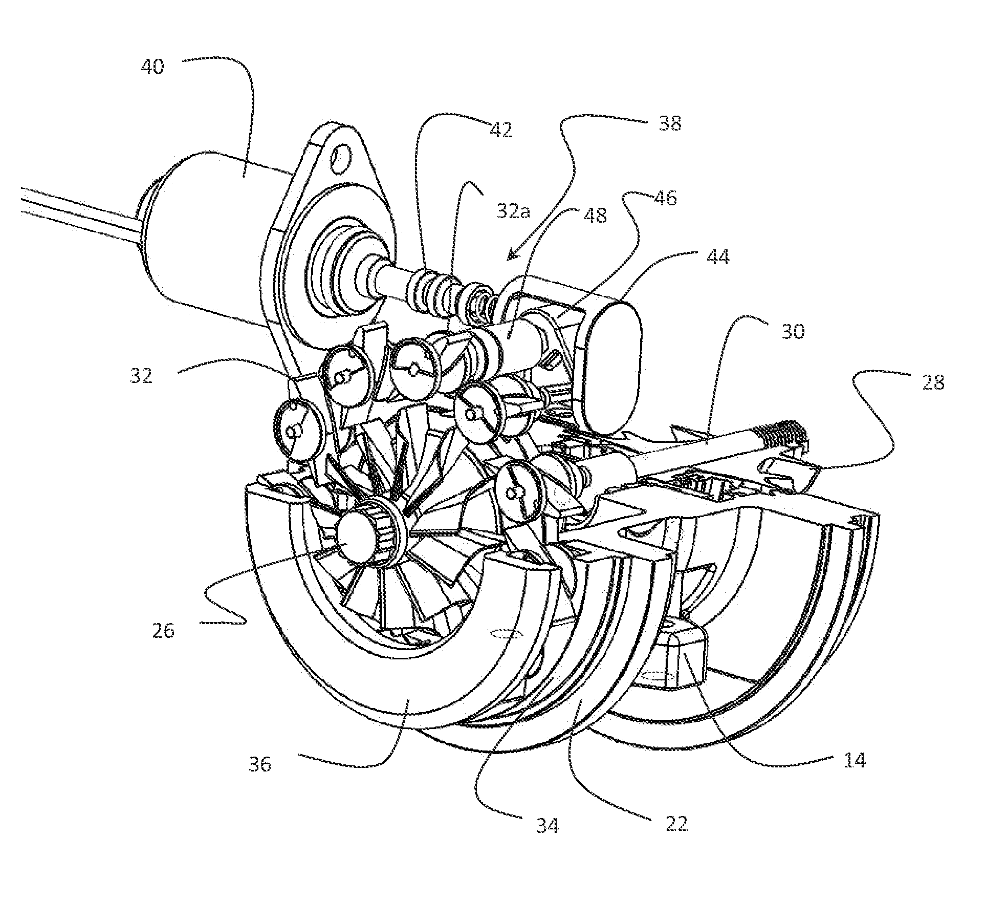
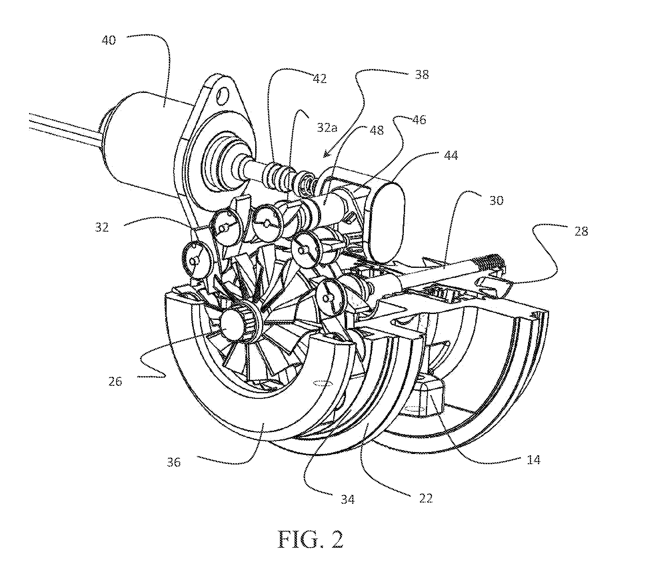
[0035]Referring to the drawings, FIG. 1 show a turbocharger 10 having a turbine assembly 12, a center housing 14 and a compressor assembly 16. The turbine assembly 12 is contained within a turbine housing 18 and the compressor assembly is contained within a compressor housing 20 which are attached to the center housing 14. FIG. 2 shows the turbocharger 10 with the turbine housing and compressor housing ...


PUM


Abstract

A variable geometry turbine (VGT) for turbochargers incorporates a turbine nozzle having a plurality of vanes, each vane having an airfoil with an inner disc and an outer disc. A first nozzle plate incorporates pockets to receive the inner discs with the inner discs substantially flush with a nozzle surface on the first nozzle plate. A second nozzle plate has pockets to receive the outer discs with outer discs substantially flush with a second nozzle surface. An integral actuation system rotates the plurality of vanes for variation of the nozzle geometry.

Description

BACKGROUND OF THE INVENTION[0001]Field of the Invention[0002]This invention relates generally to the field of charge air boosting of internal combustion engines and more particularly to a variable geometry turbine employing balanced variable vanes and a hydraulic servo driven by a proportional solenoid for vane closing with a reaction spring for vane opening.[0003]Description of the Related Art[0004]Variable Geometry Turbines (VGT) for turbochargers have become very popular in various automotive and truck market segments over the past 20 years. All major turbocharger manufacturers now have VGTs in production. The capability of the VGT to increase the controllability of the air flow to the engine has proven to be of great value to certain engine market segments. The VGT can be used to vary the air fuel ratio (AF), improve the transient response of the turbocharger, provide additional back pressure to the engine to drive external cooled EGR, and / or provide additional back pressure to ...

Claims


Application Information

Patent Timeline
IPC IPC(8): F02B37/22F04D27/00F04D17/10
CPCF02B37/22F04D27/002F04D17/10F02B37/24Y02T10/12
Inventor ARNOLD, STEVEN DONHANG, WANGYANZHAO, LIXIN, XIAOFEN
Owner KANGYUE TECH
Learn More