
Engine Control Device

a control device and engine technology, applied in the direction of electric control, machines/engines, mechanical equipment, etc., can solve the problems of deterioration of lubrication performance, and achieve the effect of preventing excessive heating or insufficient heating, and facilitating vaporization

Active Publication Date: 2017-01-12
HITACHI ASTEMO LTD
View PDF13 Cites 9 Cited by
  • Summary
  • Abstract
  • Description
  • Claims
  • Application Information

AI Technical Summary

Benefits of technology

The invention allows for the proper management of engine oil temperature when fuel with mixed composition, such as gasoline or mixed fuel, is used. This is helpful in preventing excessive heating or insufficient heating, which leads to reduced fuel efficiency and increased lubricant consumption. The engine control device adjusts the oil temperature accordingly, resulting in better fuel vaporization and improved lubrication performance.

Problems solved by technology

As a result, the engine oil is diluted by the fuel (hereinafter called oil dilution), and lubrication performance is deteriorated.

Method used


Image

  • Engine Control Device
  • Engine Control Device
  • Engine Control Device

Examples


Embodiment Construction

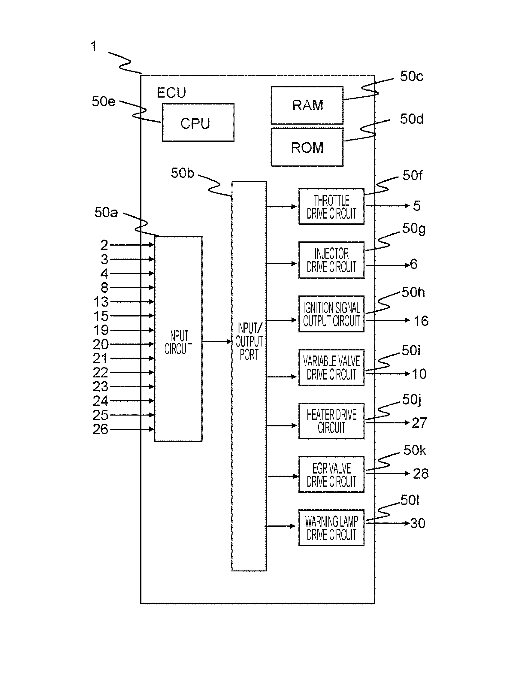
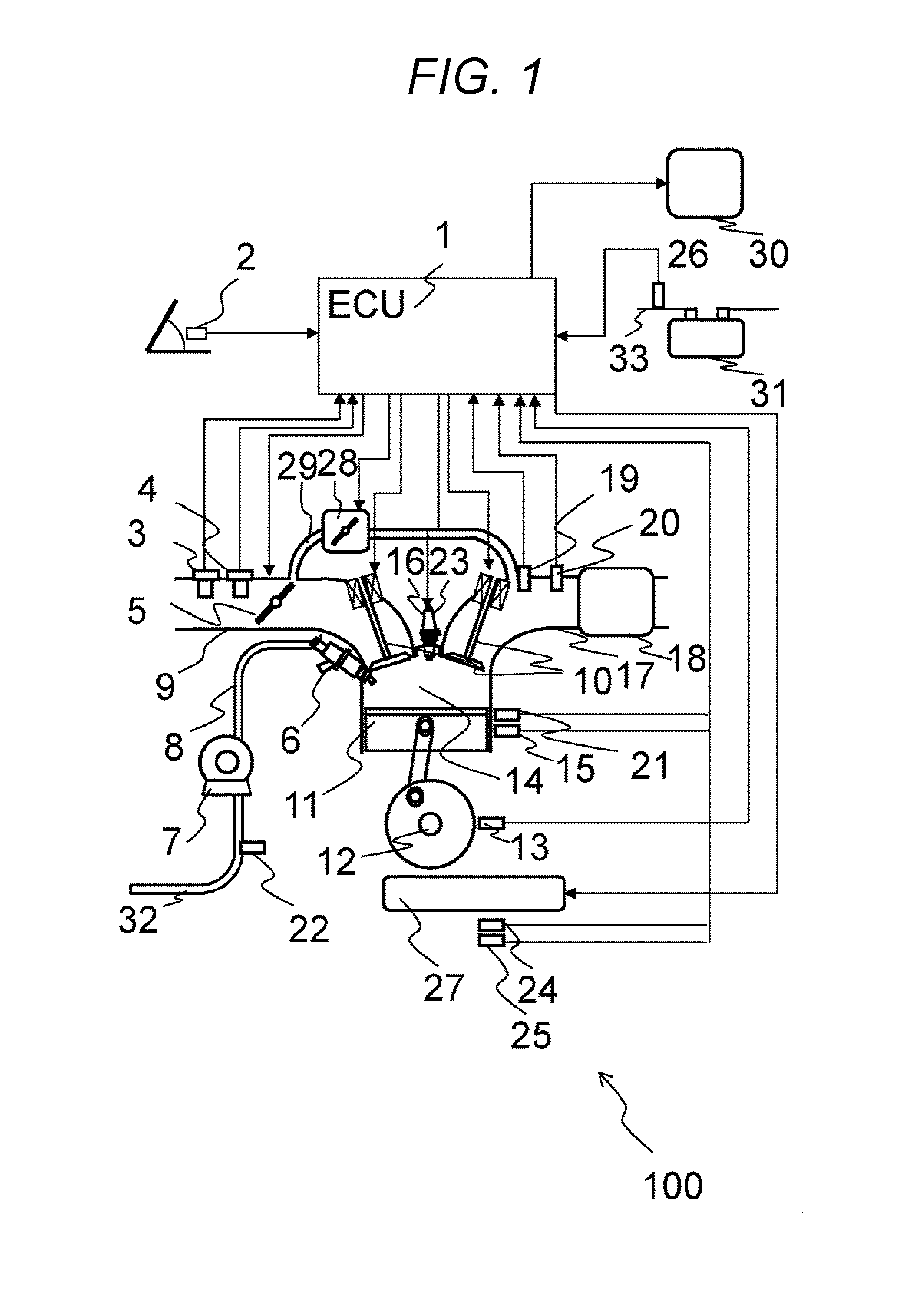
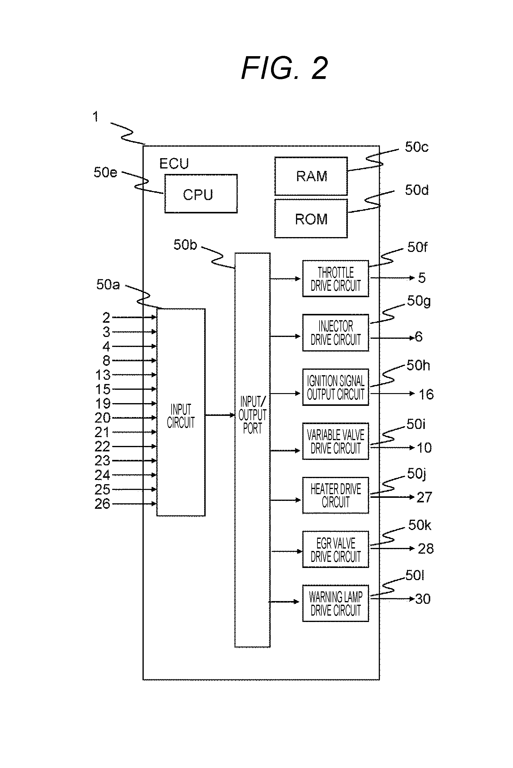
[0045]A configuration and an operation of the engine control device according to the present invention will be described below with reference to FIGS. 1 to 23.

[0046]FIGS. 1 to 23 describe a configuration of a system in which a control device is used in a vehicle engine. The control device controls a temperature of oil lubricating the interior of the engine and controls the oil temperature based on a detection result of the property of fuel being supplied to the engine.

[0047]FIG. 1 is a system configuration view of a vehicle engine system according to an embodiment described herein. An engine 100 is a vehicle engine which performs a spark-ignition combustion. Each of en air flow sensor 3, a throttle 5, and an intake air temperature / humidity sensor 4 is provided at an appropriate position of an intake pipe 9. The air flow sensor 3 measures an intake air amount. The throttle 5 adjusts an intake pipe pressure. The intake air temperature / humidity sensor 4 is one mode of an intake air tem...


PUM


Abstract

An engine control device sets a target value for the engine oil temperature appropriately in an engine that uses gasoline as a fuel, even when the fuel does not have a single boiling point because the gasoline is a mixed composition, or when the fuel property changes (for example, when the vaporization property changes due to deterioration). In other words, the engine control device prevents excessive heating or insufficient heating by changing the oil temperature to the high side in a condition wherein the fuel being used does not easily vaporize, and changing the oil temperature to the low side in a condition wherein the fuel being used easily vaporizes. This engine control device includes an oil temperature controller that controls the temperature of oil lubricating the interior of the engine; a fuel supply device that supplies fuel to the engine; and a detector for detecting the property of the fuel. The temperature of the oil is controlled on the basis of a signal from the detector.

Description

DESCRIPTION[0001]Technical Field[0002]The present invention relates to an engine control device mounted in such as a vehicle.[0003]Background Art[0004]Current vehicles are strongly required to reduce fuel consumption from the viewpoint of environmental protection. As a unit that reduces the fuel consumption, a downsized engine including a cylinder direct injection fuel supply device is being developed. The cylinder direct injection fuel supply device directly injects fuel in a combustion chamber by using a fuel injection valve (hereinafter called an injector) and can suppress abnormal combustion by cooling in the combustion camber. By suppressing the abnormal combustion, an engine can be downsized, and fuel consumption can be reduced. In the above-described downsized engine, a combustion chamber capacity is reduced, and a distance between the above-described injector and a wall surface is shortened. Therefore, injected fuel is easily attached on a piston crown surface and a wall sur...

Claims


Application Information

Patent Timeline
IPC IPC(8): F01M5/00H05B1/02F02D41/22
CPCF01M5/005F01M5/001F02D2041/224H05B1/0236F02D41/22F02D41/0025F02D41/003F02D2200/023F02D2200/0611F02D2250/08F02D2250/11F02D35/026
Inventor OGATA, KENICHIROHOKAMOTO, TAKASHIARIHARA, YOSHINOBUSUKEGAWA, YOSHIHIRO
Owner HITACHI ASTEMO LTD
Learn More