Dental light curing device

a curing device and dental technology, applied in dental prosthetics, dental surgery, medical science, etc., can solve the problems of difficult to meet the requirements of implementation, unsatisfactory cooling effect, and large amount of waste heat generated by leds

Active Publication Date: 2017-01-12
MONITEX IND
View PDF12 Cites 3 Cited by
  • Summary
  • Abstract
  • Description
  • Claims
  • Application Information

AI Technical Summary

Benefits of technology

This patent text describes an invention which solves the problem of ineffective cooling in conventional techniques by providing a cooling structure for a light emitting module. The invention has a cooling passage and a cooling fan, which allows the cooling airflow to pass through the cooling passage and evacuate the waste heat generated by the light emitting chip. The primary heat sink is located only in the second zone of the installation space, making it smaller and easier to change the profile. Overall, this invention provides more efficient cooling and greater flexibility in installation compared to conventional techniques.

Problems solved by technology

As a result, a greater amount of waste heat also is generated from the LED.
In practice, the air fan is located on the secondary heat sink remote from the primary heat sink, and can only provide cooling airflow to do heat exchange for the surface of the secondary heat sink.
The cooling efficacy is not desirable.
In addition, the elongate secondary heat sink takes a greater portion of the interior space of the dental curing light that limits arrangement of other elements.
This also makes changing the size and shape of the dental curing light to meet implementation requirements more difficult.

Method used


Image

  • Dental light curing device
  • Dental light curing device
  • Dental light curing device

Examples


Embodiment Construction

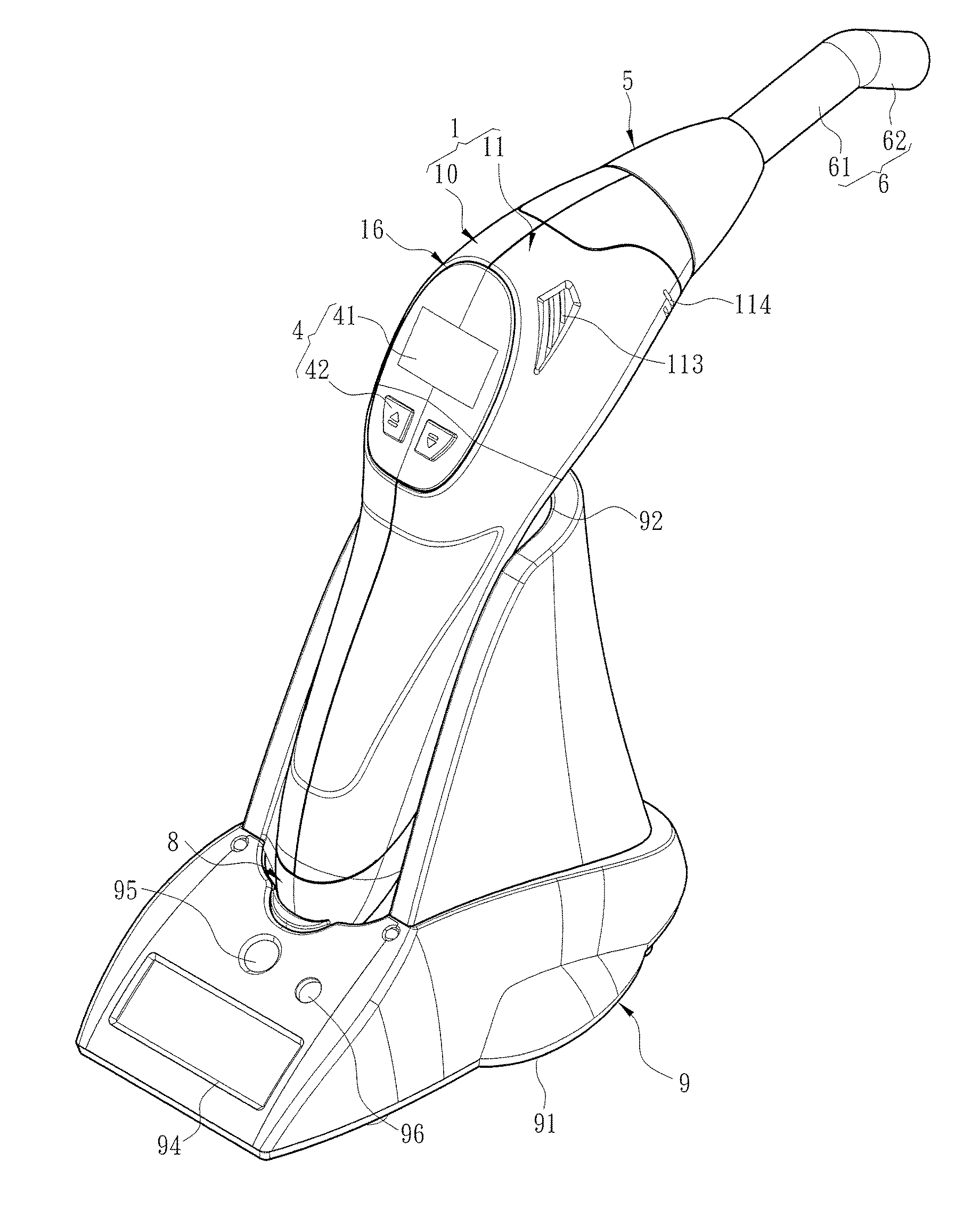
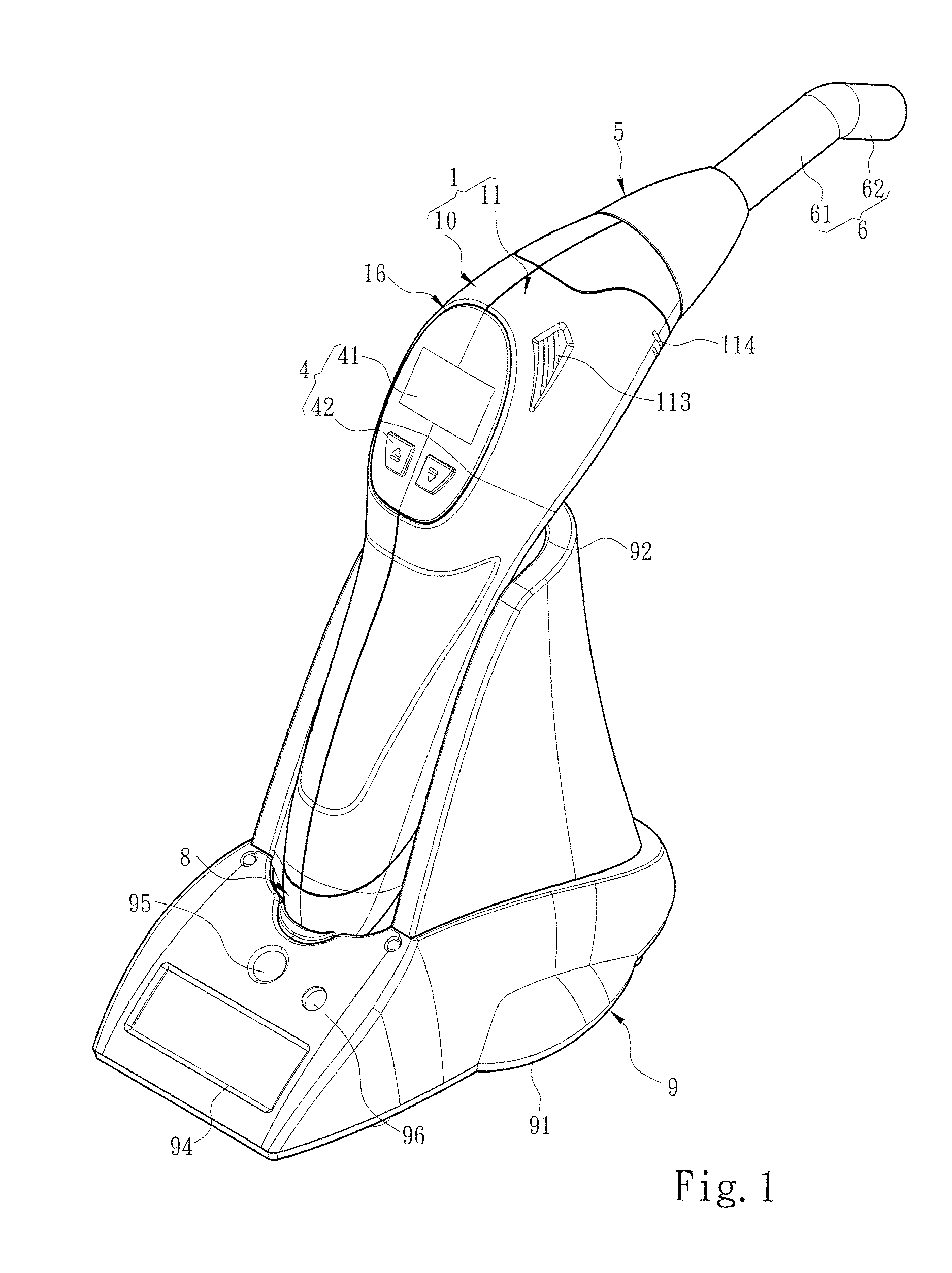
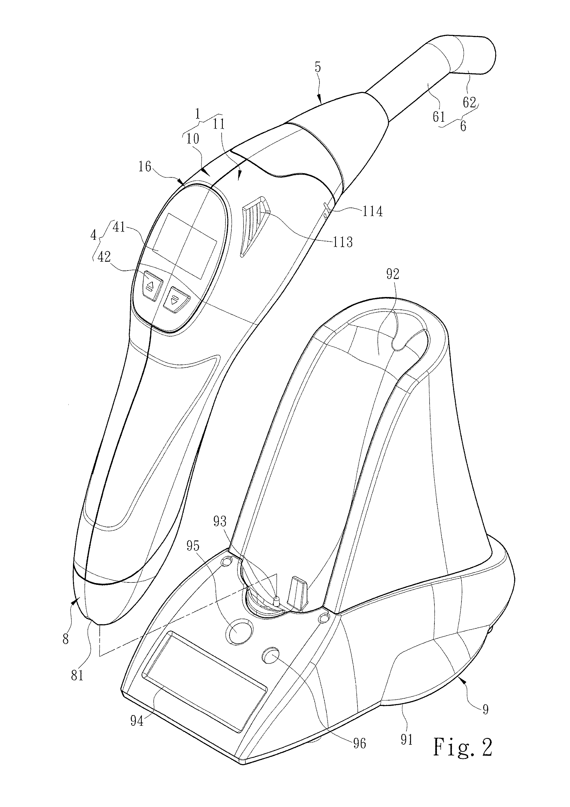
[0027]Please referring to FIGS. 1 through 6, the present invention aims to provide a dental light curing device that includes a shell 1, and a light emitting module 2 and a duty module 3 located in the shell 1. The shell 1 further includes a first shell segment 10 and the second shell segment 11 that are designed and structured in a symmetrical manner, and made through a mechanical fabrication process such as injection forming such that the first shell segment 10 and the second shell segment 11 can be assembled through latching, bonding, screw fastening or the like. Furthermore, after the first shell segment 10 and the second shell segment 1 are assembled, they jointly define an installation space 12 and an assembly opening 13 communicating with the installation space 12. The first shell segment 10 has a first support rib 101 and a first confining rib 102 that are integrally formed and face the second shell segment 11. The first confining rib 102 is located between the first support...


PUM


Abstract

A dental light curing device includes a first shell segment, a second shell segment coupled with the first shell segment to jointly define an installation space, and a light emitting module and a duty module located in the installation space. The first shell segment and the second shell segment have respectively a first confining rib and a second confining rib to divide the installation space into a first zone and a second zone. The light emitting module is located in the second zone to form electric connection with the duty module and be controlled to generate a curing light. The light emitting module includes a primary heat sink, a secondary heat sink located on the primary heat sink and a light emitting chip located on the secondary heat sink. The primary heat sink is hollow and includes a cooling passage and a cooling fan located in the cooling passage.

Description

FIELD OF THE INVENTION[0001]The present invention relates to a dental light curing device and particularly to a dental light curing device equipped with a light emitting module which holds a primary heat sink and a secondary heat sink and a cooling fan embedded on the primary heat sink.BACKGROUND OF THE INVENTION[0002]In the conventional dental surgery and therapeutic process medical people often take a suitable treatment for a patient according to the condition of the patient's decayed tooth. In the event that the decayed condition is minor, a commonly called filling treatment usually is taken to prevent the decayed tooth from deteriorating. At the present filling treatment a filling material (such as dental amalgam, resin or ceramic artificial enamel) is filled in the patient tooth, then filling material is cured to finish the treatment. In the followings the resin is used as an embodiment of the filling material to facilitate discussion. In the filling treatment patient's tooth i...

Claims


Application Information

Patent Timeline
IPC IPC(8): A61C13/15A61C1/00
CPCA61C1/0015A61C19/004
Inventor WANG, SHU-LUNG
Owner MONITEX IND
Why Eureka
Try Eureka