
Passive cooling system of containment building and nuclear power plant comprising same

a technology of containment building and nuclear power plant, which is applied in nuclear engineering, greenhouse gas reduction, nuclear elements, etc., can solve the problems of reducing the performance of heat exchangers, difficulty in layout, and inefficient supply of steam, so as to facilitate the maintenance of pressure boundaries, reduce size, and high heat exchange performance

Active Publication Date: 2017-01-05
KOREA ATOMIC ENERGY RES INST
View PDF10 Cites 5 Cited by
  • Summary
  • Abstract
  • Description
  • Claims
  • Application Information

AI Technical Summary

Benefits of technology

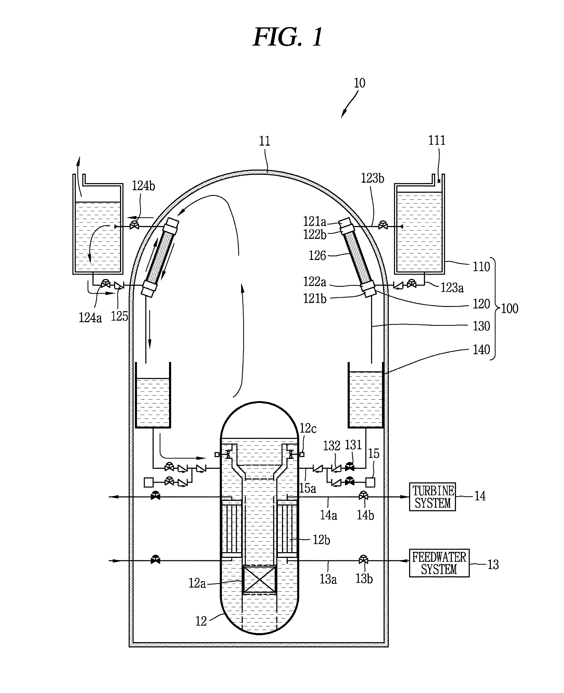
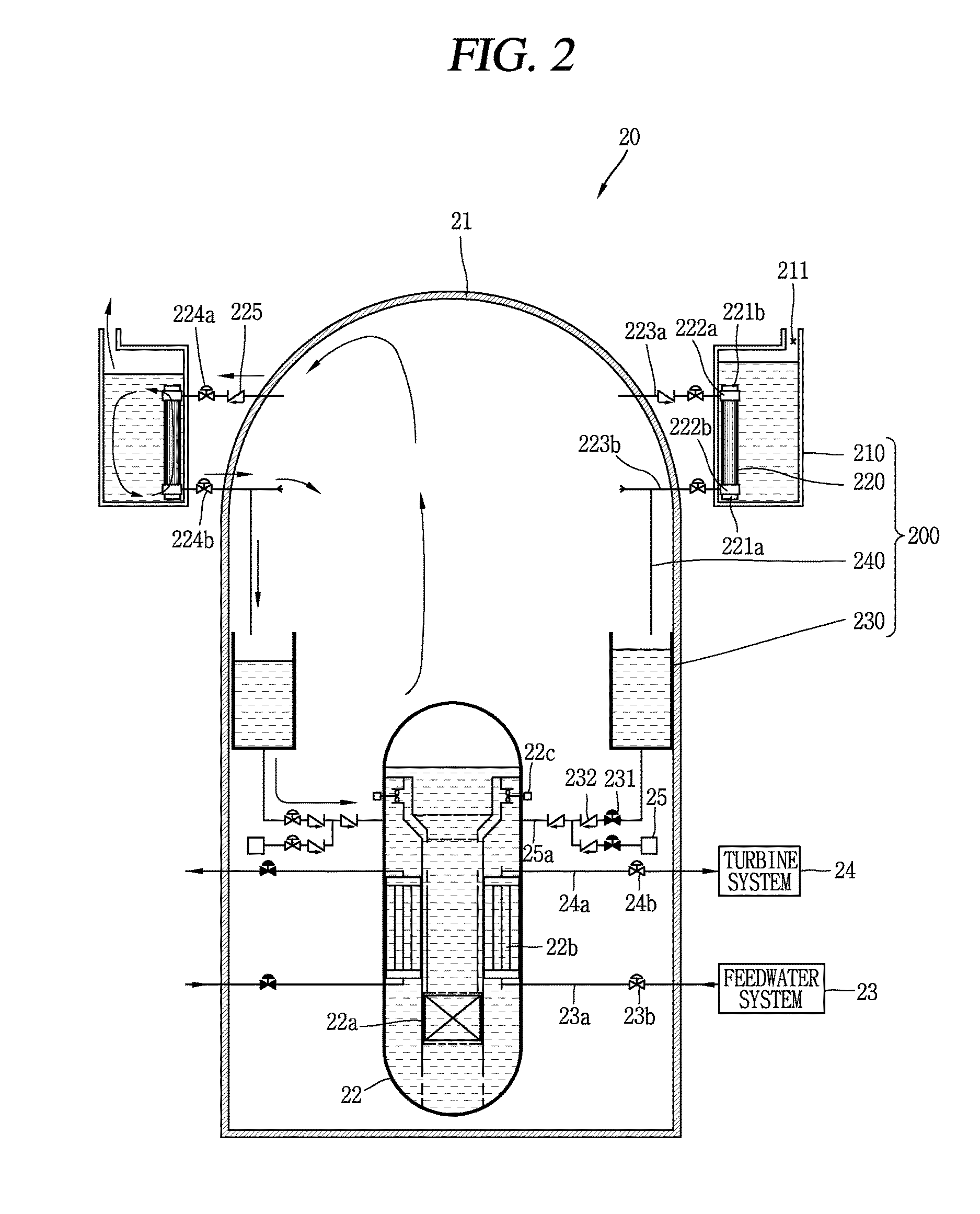
The present invention proposes a cooling system for a nuclear power plant's containment building that uses a plate type heat exchanger to enhance the heat exchange performance. This system is passive, meaning it uses natural convection to cool the building. The system safely injects condensate collected during the cooling process into a reactor coolant system. The plate type heat exchanger is durable in high-temperature, high-pressure environments, making it easier to maintain the pressure boundary between the primary and secondary fluids and reducing the size of the system while still complying with design standards on an earthquake load or the like. Additionally, the high integration of the plate type heat exchanger allows for a reduction in weight and size, alleviating layout problems within the containment building.

Problems solved by technology

When atmosphere is not efficiently circulated, steam may not be efficiently supplied thereto, thereby reducing the performance of the heat exchanger.
Furthermore, a lot of devices and structures may be disposed within a containment building in a nuclear power plant in which a containment building cooling heat exchanger is disposed within a containment building, and thus there is a difficulty in the layout, and thus reduction in size and weight is required.

Method used


Image

  • Passive cooling system of containment building and nuclear power plant comprising same
  • Passive cooling system of containment building and nuclear power plant comprising same
  • Passive cooling system of containment building and nuclear power plant comprising same

Examples


Embodiment Construction

[0027]Hereinafter, a passive containment building cooling system associated with the present disclosure will be described in more detail with reference to the accompanying drawings. Even in different embodiments according to the present disclosure, the same or similar reference numerals are designated to the same or similar configurations, and the description thereof will be substituted by the earlier description. Unless clearly used otherwise, expressions in the singular number used in the present disclosure may include a plural meaning.

[0028]A plate type heat exchanger in the present disclosure may refer to all plate type heat exchangers when there is any difference in the processing method or bonding method of a plate thereof as well as a typical plate type heat exchanger and a printed circuit type heat exchanger, unless otherwise specified in particular. Furthermore, a containment building in the present disclosure may collectively refer to a containment building, a reactor buil...


PUM


Abstract

The present invention discloses a passive cooling system of a containment building, to which a plate-type heat exchanger is applied. A passive cooling system of a containment building comprises: a containment building; a plate-type heat exchanger provided to at least one of the inside and the outside of the containment building and comprising channels respectively provided to the both sides of a plate so as to be arranged dividedly from each other such that the plate-type heat exchanger carries out mutual heat exchange between the internal atmosphere of the containment building and a heat exchange fluid while maintaining a pressure boundary; and a pipe connected to the plate-type heat exchanger by penetrating the containment building so as to form the path of the internal atmosphere of the containment building or the heat exchange fluid.

Description

BACKGROUND OF THE INVENTION[0001]1. Field of the Invention[0002]The present disclosure relates to a passive cooling system of a containment building to which a plate-type heat exchanger is applied and a nuclear power plant including the same.[0003]2. Description of the Related Art[0004]Reactors are divided into active reactors using active power such as a pump and passive reactors using passive power such as gravity force, gas pressure according to the configuration method of a safety system. Furthermore, reactors are divided into loop type reactors (for example, Korean pressurized water reactor) in which a main component (a steam generator, a pressurizer, a pump impeller, etc.) is installed at an outside of the reactor vessel and integrated type reactors (for example, SMART reactor) in which the main component is installed at an inside of the reactor vessel according to the installation location of the main component.[0005]In the nuclear power plant industry, a passive containment ...

Claims


Application Information

Patent Timeline
Patent Type & Authority Applications(United States)
IPC IPC(8): G21C15/18G21D1/02G21C9/004
CPCG21C9/004G21D1/02G21C15/18Y02E30/30Y02E30/00G21C9/012
Inventor KIM, YOUNG INPARK, CHEON TAERYU, SEUNG YEOBBAE, YOUNG MINMOON, JOO HYUNGSHIN, SOO JAIHAN, HUN SIKKANG, KYUNG JUNKIM, YOUNG SOOKIM, TAE WANYOON, JU HYEONKIM, KEUNG KOOHA, JAE JOO
Owner KOREA ATOMIC ENERGY RES INST
Learn More