Gravity sensing flashlight and its electric control circuit

a gravity sensing flashlight and electric control circuit technology, applied in the field of light, can solve the problems of low relay ability of the flashlight and even reduced service life, and achieve the effects of prolonging the service life of the battery, saving energy, and improving the air tightness

Inactive Publication Date: 2016-12-29
NINGBO FUTAI ELECTRIC CO LTD
View PDF11 Cites 12 Cited by
  • Summary
  • Abstract
  • Description
  • Claims
  • Application Information

AI Technical Summary

Benefits of technology

[0007]For mounting convenience, the tail cover is in detachable connection to the cylindrical body; meanwhile, to improve the air-tightness between the tail cover and the cylindrical body, a sealing ring is provided between the tail cover and the cylindrical body. An electric control circuit for the gravity sensing flashlight is provided, comprising a power supply circuit, a current chip circuit, a gravity sensing circuit and an LED lamp bead circuit, wherein the current chip circuit is in signal connected to the gravity sensing circuit through a switch; the power supply circuit comprises a power supply chip; the current chip circuit comprises a current chip; the gravity sensing circuit comprises a gravity sensing chip; and, the LED lamp bead circuit comprises an LED lamp, a field effect transistor and a first resistor.
[0008]In the gravity sensing flashlight provided by the present invention, the switch not only may turn on or off the power supply, but also may switch the operating mode of the flashlight. When the flashlight is at a normal mode, three different modes, i.e., a high mode, a low mode and a flashing mode, may be controlled by the switch. Here, the three modes are switched by the knockout rod in the switch. When the flashlight is switched to an automatic mode, the flashlight may automatically judge and adjust brightness according to the change in action of a user in using the flashlight at a far / near distance, thereby realizing the effects of saving energy and prolonging the service life of a battery. In the actual use of the product, during a switchover between far distance illumination and near distance illumination, by virtue of the change of this action, a gravity sensor sends a signal to the current chip controller to adjust the current, thereby achieving the purpose of automatically adjusting brightness, greatly saving the electric quantity of the battery and prolonging the service life of the battery. Meanwhile, the internal structures of the gravity sensing flashlight are fixed layer by layer, so the LED lamp bead may be stably disposed in the flashlight.

Problems solved by technology

As the brightness of an prior art flashlight is fixed or its brightness adjustment will not be automatically changed according to environmental needs, the relay ability of the flashlight is low and the service life is even reduced due to the use in high brightness.

Method used


Image

  • Gravity sensing flashlight and its electric control circuit
  • Gravity sensing flashlight and its electric control circuit
  • Gravity sensing flashlight and its electric control circuit

Examples


embodiment 1

[0054]

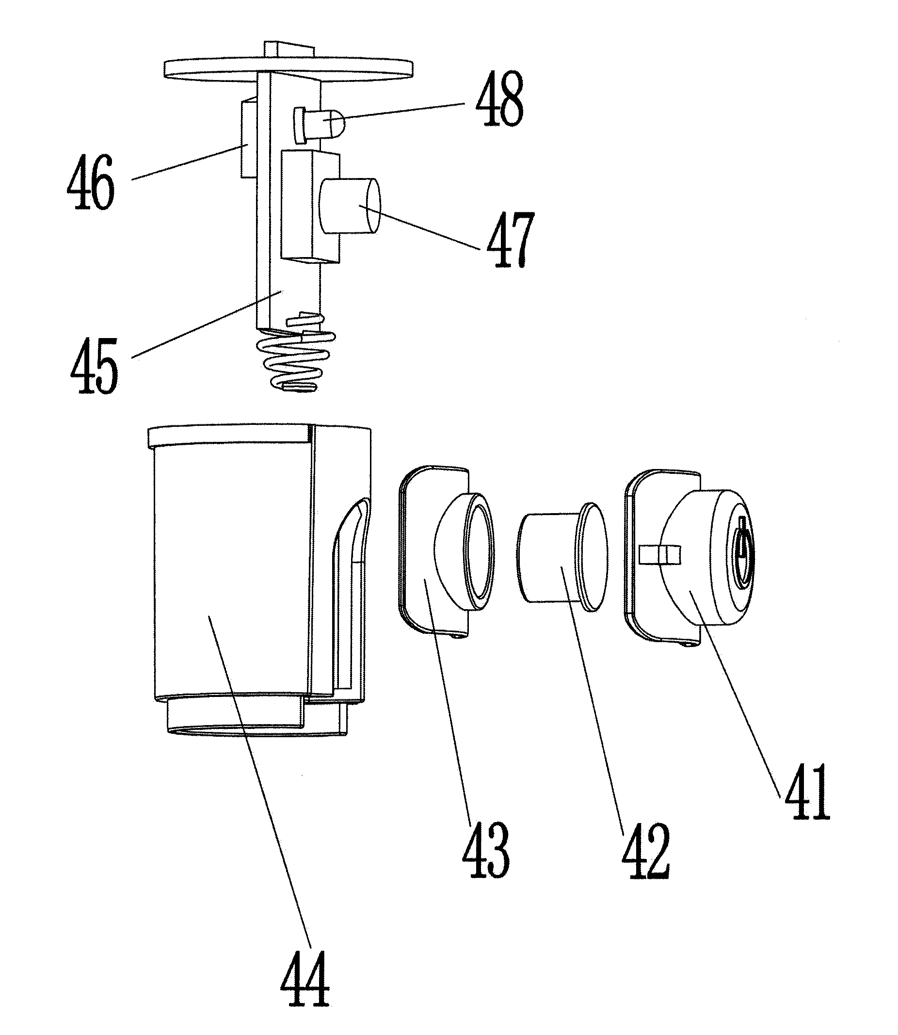
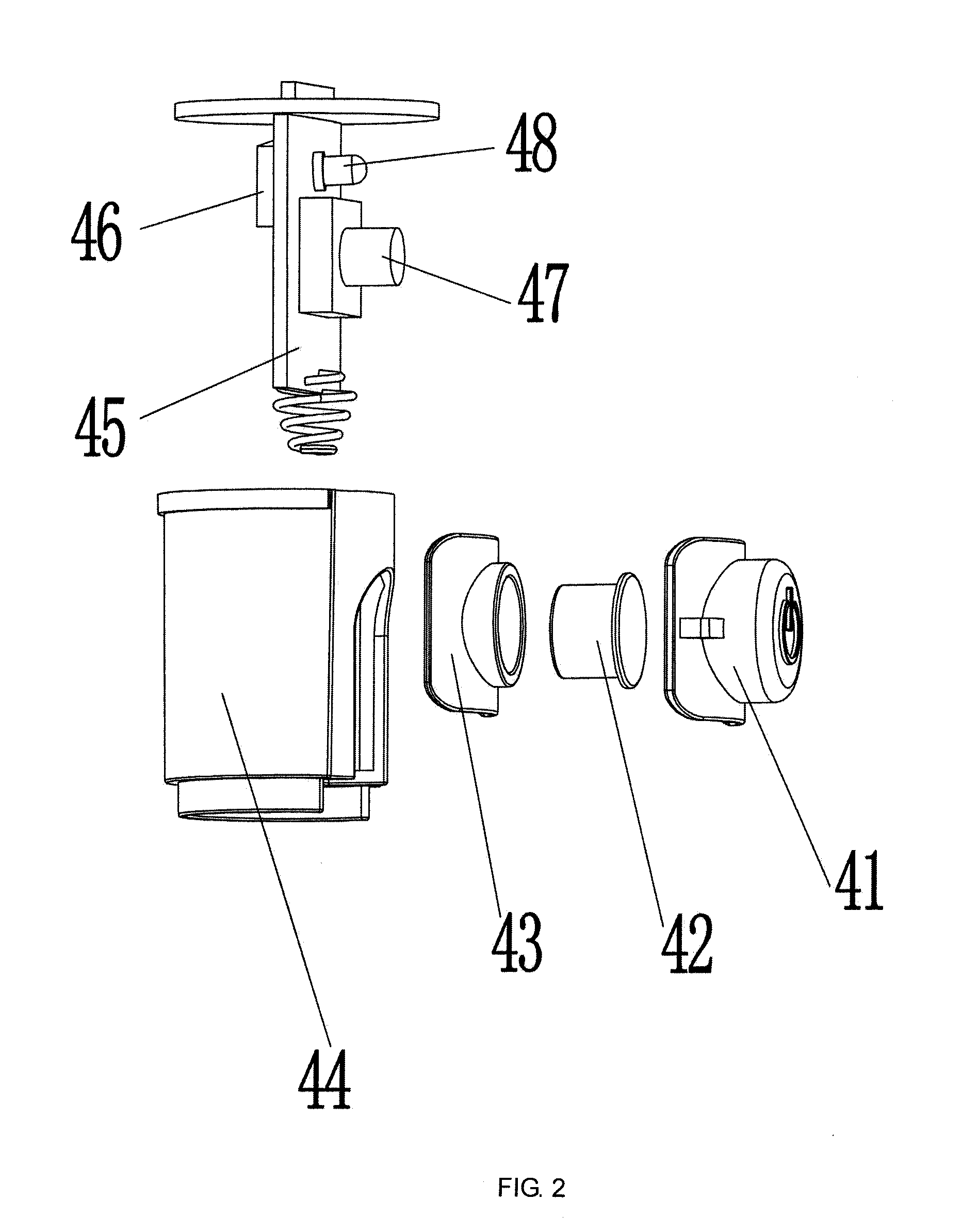
[0055]As shown in FIG. 1, FIG. 2 and FIG. 3, this embodiment provides a gravity sensing flashlight, comprising a lamp holder 1, a cylindrical body 2 and a tail cover 3, the lamp holder 1 being connected to a head end of the cylindrical body 2, the tail cover 3 being connected to a tail end of the cylindrical body 2, a storage battery as a power supply being internally provided in the cylindrical body 2, a switch 4 being additionally mounted on a side wall of the cylindrical body 2, wherein the switch 4 consists of a switch leather sheath 41, a knockout rod 42, a knockout rod fixing frame 43 and a circuit board fixing frame 44 in turn from inside to outside, with a circuit board 45 being mounted on the circuit board fixing frame 44, and a gravity sensor 46, a switch button 47 and an indicator light 48 being provided on the circuit board 45; and, the lamp holder 1 consists of a shell cap 11, a shell body 12 and a shell base 13 which are in threaded connection to each other, with...

embodiment 2

[0058]

[0059]As shown in FIG. 6, this embodiment provides a gravity sensing flashlight and a control circuit. The general structure is the same as Embodiment 1, but when in specific use, to fix an LED lamp bead in the cylindrical body of the flashlight more steadily, a mounting bracket 6 consisting of more than three arc surfaces 5 is provided on the shell base 13 of the lamp holder 1. An adjusting base 7 is sheathed outside the mounting bracket 6, and a rotating base 8 inserted inside the mounting bracket 6. A lug 9 is provided on the rotating base 8, with the width of the lug 9 being the same as the width of a gap between the arc surfaces 5. A conical surface which may be fitted with the lamp bead fixing frame 17 in the shell body 12 is provided at an upper end of the rotating base 8. The outer side of the adjusting base 7 is a hexagon or an octagon. The specific installation is as follows: the lug 9 on the rotating base 8 is first clamped on the mounting bracket 6 of the shell bas...

embodiment 3

[0060

[0061]As shown in FIG. 7, this embodiment provides a gravity sensing flashlight and a control circuit. The general structure is the same as Embodiment 2, but when in specific use, for mounting convenience, the tail cover 3 is in detachable connection to the cylindrical body 2; meanwhile, to improve the air-tightness between the tail cover 3 and the cylindrical body 2, a sealing ring 10 is provided between the tail cover 3 and the cylindrical body 2.


PUM


Abstract

The present invention discloses a gravity sensing flashlight, including a lamp holder, a cylindrical body and a tail cover, the lamp holder being connected to a head end of the cylindrical body, the tail cover being connected to a tail end of the cylindrical body, a storage battery as a power supply being internally provided in the cylindrical body, a switch being additionally mounted on a side wall of the cylindrical body, a circuit board being mounted in the switch, a gravity sensor and an indicator light being provided on the circuit board; the lamp holder consists of a shell cap, a shell body and a shell base which are in threaded connection to each other, a lens, a lens holder, an LED lamp bead and a lamp bead fixing frame being mounted in the shell body, a current chip controller being mounted on the lamp bead fixing frame, one end of the current chip controller being connected to the LED lamp bead while the other end thereof being connected to the gravity sensor. The gravity sensing flashlight provided by the present invention can automatically judge and adjust brightness according to the change in action of a user in using the flashlight at a far/near distance, thereby realizing the effects of saving energy and prolonging the service life of a battery.

Description

TECHNICAL FIELD[0001]The present invention relates to the lighting field, in particular to a gravity sensing flashlight and its electric control circuit.BACKGROUND OF THE PRESENT INVENTION[0002]Through researches on people's daily action habits of using a flashlight, it has been found that people's hands holding the flashlight will generate a downward action when the flashlight is used to illuminate a near distance, because quite bright light is not required at this time; however, people's hands holding the flashlight will generate an upward action when the flashlight is used to illuminate a far distance, so that it is indicated that highest brightness is required at this time. As the brightness of an prior art flashlight is fixed or its brightness adjustment will not be automatically changed according to environmental needs, the relay ability of the flashlight is low and the service life is even reduced due to the use in high brightness.SUMMARY OF THE PRESENT INVENTION[0003]The obj...

Claims


Application Information

Patent Timeline
Patent Type & Authority Applications(United States)
IPC IPC(8): H05B33/08F21V23/04F21L4/00H05B44/00
CPCH05B33/0848F21Y2115/10F21V23/0414F21L4/00F21L4/027F21V23/0442H05B45/14
Inventor QIU, FUJUN
Owner NINGBO FUTAI ELECTRIC CO LTD
Why Eureka
Try Eureka