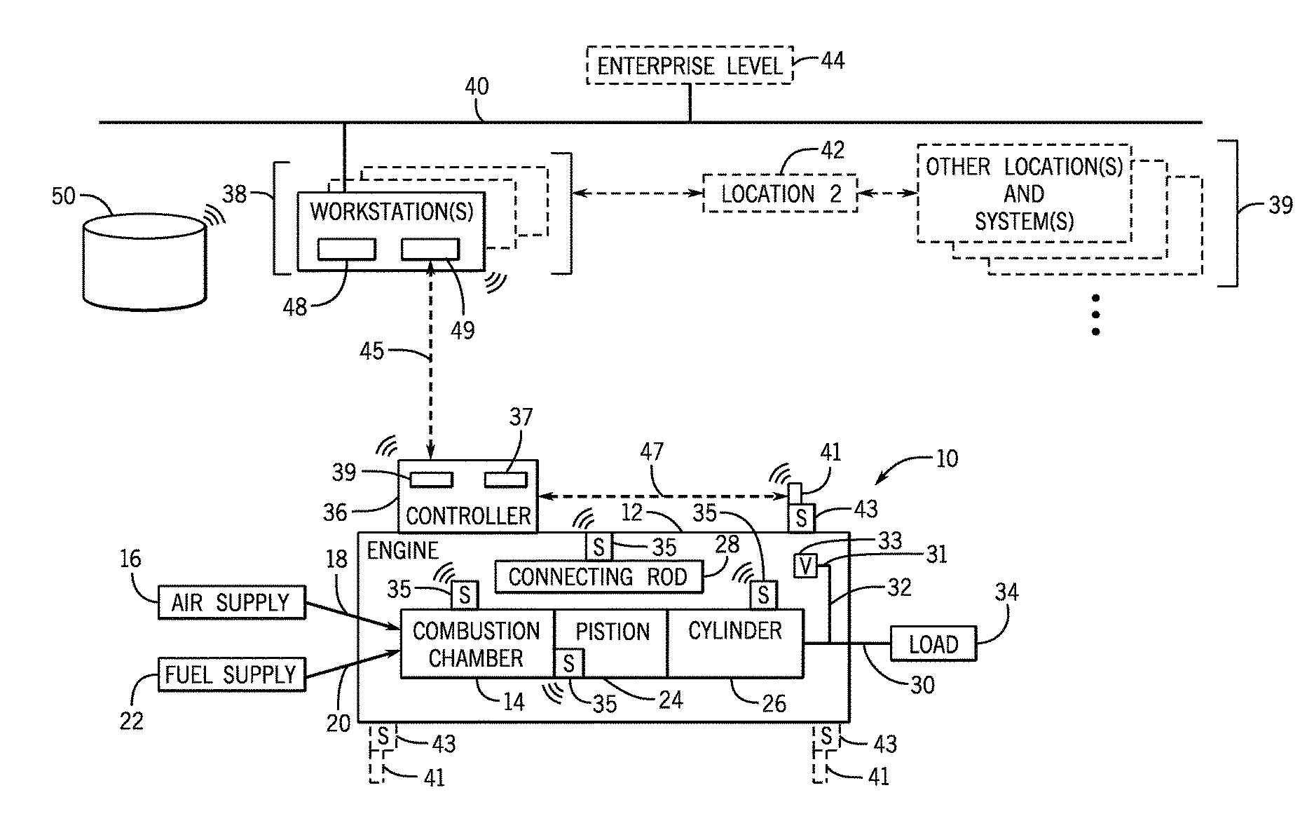
Method and system for portable engine health monitoring

a portable engine and health monitoring technology, applied in the field of engine monitoring, can solve the problems of undesirable engine maintenance events, inefficient operation, and the inability of sensors that are used to detect certain faults, and achieve the effect of avoiding the placement of sensors in appropriate places or locating them on the engin

Inactive Publication Date: 2016-12-29
AI ALPINE US BIDCO INC
View PDF9 Cites 30 Cited by
  • Summary
  • Abstract
  • Description
  • Claims
  • Application Information

AI Technical Summary

Benefits of technology

The patent describes a system that can detect and synchronize vibration signals of an engine's rotating components. This system can use computer-readable media to store instructions for analyzing the engine's rotation timing and vibration signals. It can also generate a graphical user interface (GUI) that shows the synchronized vibration signals at different positions in relation to time, allowing for better identification and troubleshooting of any potential faults. Additionally, the patent describes an apparatus that includes a sensor for detecting vibration signals and transmitting them for analysis. The technical effects of this patent include improved detection and synchronization of vibration signals, improved troubleshooting of engine faults, and improved monitoring of engine performance.

Problems solved by technology

As the engines are used over time, their components may deteriorate and lead to inefficient operation and / or an undesirable maintenance event of the engine.
However, the sensors that are used typically may not be placed in appropriate places or relocated on the engines to detect certain faults.

Method used


Image

  • Method and system for portable engine health monitoring
  • Method and system for portable engine health monitoring
  • Method and system for portable engine health monitoring

Examples


Embodiment Construction

[0013]One or more specific embodiments of the present disclosure will be described below. In an effort to provide a concise description of these embodiments, all features of an actual implementation may not be described in the specification. It should be appreciated that in the development of any such actual implementation, as in any engineering or design project, numerous implementation-specific decisions must be made to achieve the developers' specific goals, such as compliance with system-related and business-related constraints, which may vary from one implementation to another. Moreover, it should be appreciated that such a development effort might be complex and time consuming, but would nevertheless be a routine undertaking of design, fabrication, and manufacture for those of ordinary skill having the benefit of this disclosure.

[0014]When introducing elements of various embodiments of the present disclosure, the articles “a,”“an,”“the,” and “said” are intended to mean that th...


PUM


Abstract

In one embodiment, one or more tangible, non-transitory computer-readable media stores instructions. The instructions, when executed by one or more processors, are configured to receive engine rotation timing event signals for one or more components of the engine and vibration signals indicative of movement of the one or more components, to synchronize the engine rotation timing event signals and the vibration signals to generate synchronized vibration signals, to determine whether a fault exists by comparing the synchronized vibration signals to vibration signatures, and to generate a graphical user interface (GUI) that depicts the synchronized vibration signals at angular positions of the one or more components in relation to time as the one or more components rotate during operation of the engine.

Description

BACKGROUND OF THE INVENTION[0001]The subject matter disclosed herein relates to engine monitoring and, more specifically, to methods and systems for portable engine health monitoring.[0002]Various engines (e.g., reciprocating and / or gas turbine engines) are widely used throughout many different industries. As the engines are used over time, their components may deteriorate and lead to inefficient operation and / or an undesirable maintenance event of the engine. In some instances, the engines do not include a way to monitor their health. In other instances, the engines may include non-movable, built-in sensors to monitor various characteristics of the components and the engines as a whole. However, the sensors that are used typically may not be placed in appropriate places or relocated on the engines to detect certain faults. Thus, it is desirable to enhance engine health monitoring.BRIEF DESCRIPTION OF THE INVENTION[0003]Certain embodiments commensurate in scope with the present disc...

Claims


Application Information

Patent Timeline
Patent Type & Authority Applications(United States)
IPC IPC(8): G01M15/14G01H1/00
CPCG01H1/006G01M15/14F02D41/009F02D41/28G01M15/046G01M15/12F02D2041/286F02D41/1498F02D41/22F02D2041/228Y02T10/40
Inventor BIZUB, JEFFREY JACOB
Owner AI ALPINE US BIDCO INC
Why Eureka
Try Eureka