
Image reading apparatus and image forming system

a reading apparatus and image technology, applied in the direction of electrographic process apparatus, instruments, optics, etc., can solve the problems of inability of scanners to correctly detect the color tone of images printed on the sheet, unstable luminance of light emitted from led elements, and imbalanced surface temperature of sheets

Active Publication Date: 2016-12-22
KONICA MINOLTA INC
View PDF0 Cites 8 Cited by
  • Summary
  • Abstract
  • Description
  • Claims
  • Application Information

AI Technical Summary

Benefits of technology

The image reading apparatus described in this patent has a feature that allows for faster cooling of the machine when a sheet with a coating is passed through without the need for image correction. This is achieved by increasing the speed of the fan to a higher level, which allows for better air flow and faster cooling.

Problems solved by technology

However, since the control board can be a heat generation source, the light emitted from the LED element may have an unstable luminance.
If a cooling air enters a route of conveying a sheet, there may be caused imbalance of the surface temperature of a sheet in the form of a temperature gradient.
In the case where a temperature gradient is formed on a sheet, a scanner may fail to correctly detect a color tone of an image printed on the sheet because of thermochromism which changes a color tone due to a change in temperature.
Accordingly, in the case of the prior art techniques described in Japanese Patent Published Application No. 2001-16373 and Japanese Patent Published Application No. 2011-97348, even if a scanner reads an image, there is the fear that correct color tones can not be detected from an image printed on a sheet due to thermochromism.

Method used


Image

  • Image reading apparatus and image forming system
  • Image reading apparatus and image forming system
  • Image reading apparatus and image forming system

Examples


embodiment 1

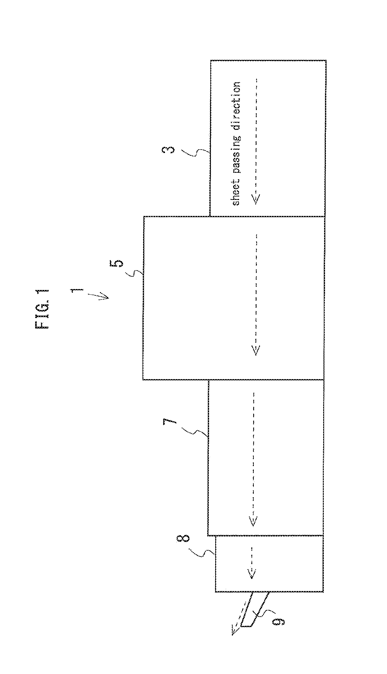
[0044]FIG. 1 is a schematic diagram for showing the overall configuration of an image forming system 1 in accordance with an embodiment 1. As illustrated in FIG. 1, the image forming system 1 includes a paper feed apparatus 3, an image forming apparatus 5, an image reading apparatus 7 and a discharge unit 8. The paper feed apparatus 3 is responsible for feeding a sheet P to the image forming apparatus 5. The image forming apparatus 5 is responsible for forming an image on a sheet P fed by the paper feed apparatus 3, i.e., printing the image on the sheet P. The image reading apparatus 7 is responsible for reading a sheet P on which an image is printed by the image forming apparatus 5, and performing various types of processing. The discharge unit 8 is provided with a catch tray 9, and discharges a sheet P, which is conveyed from the image reading apparatus 7, to the catch tray 9.

[0045]Next, the image forming apparatus 5 will be specifically explained. FIG. 2 is a diagram for showing ...

embodiment 2

[0169]In this embodiment 2, similar elements are given similar references as in the embodiment 1, and therefore no redundant description is repeated. As described below, this embodiment 2 differs from the embodiment 1 in that ducts 153 are arranged to blow out air from fans 151 in a different direction.

[0170]FIG. 15 is a view for schematically showing the situation in which a cooling air is prevented from blowing on a sheet P by ducts 153a and 153b of the embodiment 2. Namely, as illustrated in FIG. 15, the ducts 153a and 153b are installed in order to lead air to the heat sinks 143. The fans 151 are arranged in order to produce an air flow along the ducts 153a and 153b respectively. The duct 153a is arranged in order to send air from the fans 151 to point light sources 131a and 131b located in this duct without leaking air to the outside. The duct 153b is arranged in order to send air from the fans 151 to point light sources 131c and 131d located in this duct without leaking air to...

embodiment 3

[0175]In this embodiment 3, similar elements are given similar references as in the embodiments 1 and 2, and therefore no redundant description is repeated. As described below, this embodiment 3 differs from the embodiments 1 and 2 in that blocking members 155 are provided.

[0176]FIG. 16 is a view for schematically showing the situation in which a cooling air is prevented from blowing on a sheet P by the blocking members 155 of the embodiment 3. Namely, as illustrated in FIG. 16, the blocking member 155 is provided between the fan 151 and the heat sink 143 to cover the periphery of the heat sink 143 and prevent heat from being transmitted to a sheet P. The blocking member 155 blocks air propelled from the fan 151 before the air reaches a sheet P.

[0177]As described above, in the image reading apparatus 7 provided with the blocking member 155 between the fan 151 and the heat sink 143, the air propelled from the fan 151 does not blow on a sheet P. The temperature distribution of a sheet...


PUM


Abstract

An image reading apparatus capable of detecting correct color tones of an image printed on a sheet is described. The image reading apparatus includes a scanner 100, a colorimeter 103, a cooling device 145, a temperature control unit 111, and an image correction unit 113. While an image correction process is not performed, the temperature control unit 111 controls the cooling temperature to a first temperature for shifting the cooling device 145 to a predetermined cooled state. While the image correction process is performed, the temperature control unit 111 controls the cooling temperature to a second temperature for making the temperature of the sheet uniform. The image correction unit 113 obtains, while the temperature control unit 111 controls the cooling temperature to the second temperature, the correction amount of the image based on the colorimetric measurement result of the colorimeter 103 and the reading result of the scanner 100.

Description

CROSS-REFERENCE TO RELATED APPLICATIONS[0001]The present application claims priority under 35 U.S.C.§119 to Japanese Patent Application No. 2015-124599, filed Jun. 22, 2015. The contents of this application are herein incorporated by reference in their entirety.BACKGROUND OF THE INVENTION[0002]Field of the Invention[0003]The present invention relates to an image reading apparatus and an image forming system.[0004]Description of Related Art[0005]Heretofore, an image forming system consisting of an electrophotographic image forming apparatus and an image reading apparatus has been used. The image forming apparatus is capable of successively printing images on sheets. The image reading apparatus is capable of reading an image printed on a sheet and performing various types of processes. The image reading apparatus reads an image on a sheet by the use of a scanner which reads the image by irradiating the sheet with light which is emitted from a point light source.[0006]The scanner is pr...

Claims


Application Information

Patent Timeline
IPC IPC(8): H04N1/00H04N1/48H04N1/60
CPCH04N1/00984H04N1/6091G03G21/20H04N1/48H04N1/6097G03G15/5045G03G15/5062G03G15/04H04N1/6041
Inventor OOISHI, AKIHIKO
Owner KONICA MINOLTA INC
Learn More