Coil component, coil module, and method for manufacturing coil component
a technology of coil module and coil component, which is applied in the direction of transformer/inductance coil/winding/connection, inductance with magnetic core, inductance with high-frequency magnetic core, etc., and can solve the problems of difficult plating, difficult to thicken the magnetic layer, and difficult to apply plating
- Summary
- Abstract
- Description
- Claims
- Application Information
AI Technical Summary
Benefits of technology
Problems solved by technology
Method used
Image

Examples
first embodiment
[0080]A coil component according to a first embodiment of the present disclosure will be described.
(Schematic Structure of Coil Component)
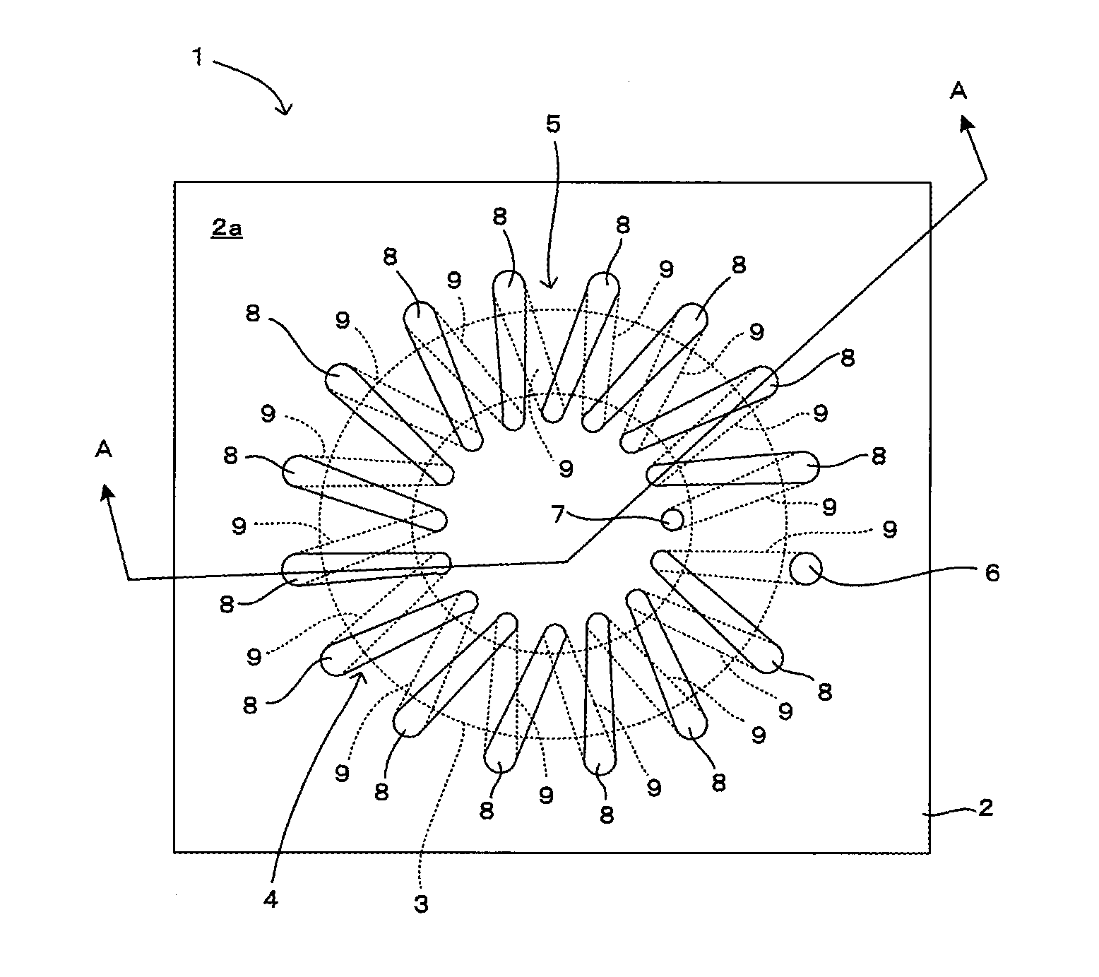
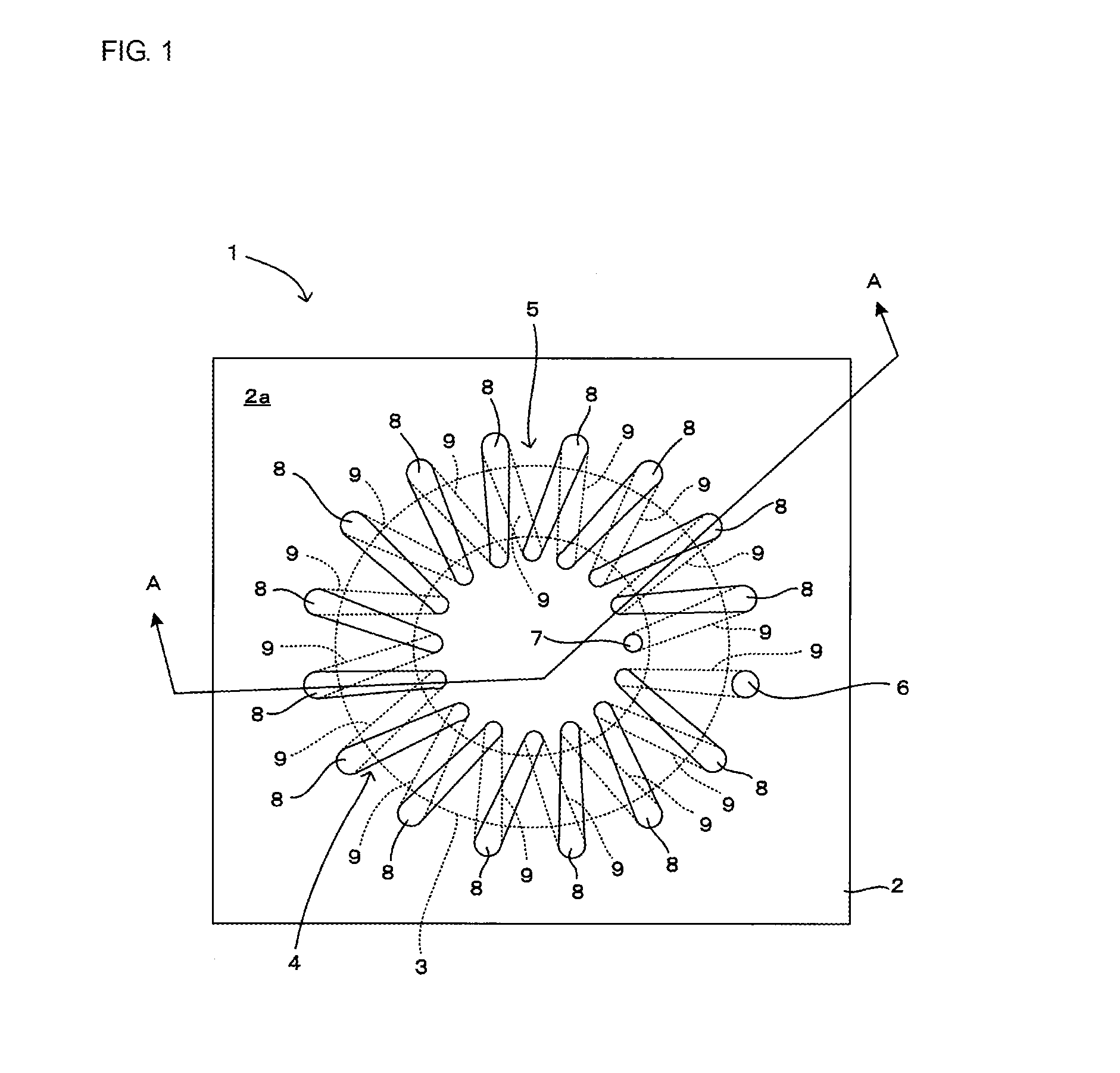
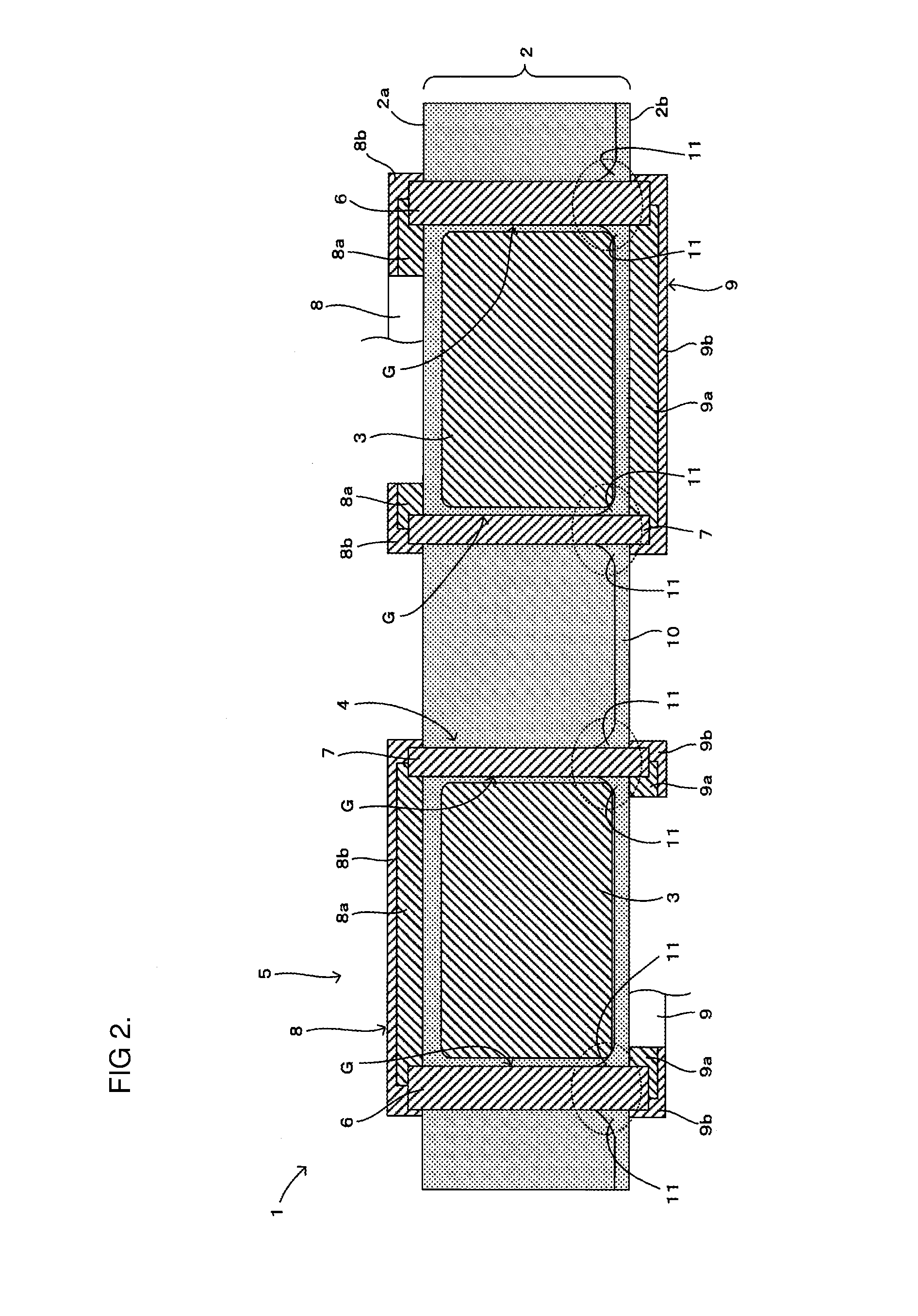
[0081]The schematic structure of a coil component 1 will be described with reference to FIGS. 1 and 2. FIG. 1 is a plan view of the coil component according to the first embodiment of the present disclosure, and FIG. 2 is a sectional view of the coil component of FIG. 1 taken along a line A-A.
[0082]As shown in FIGS. 1 and 2, the coil component 1 includes a coil 5 that has a coil core 3 embedded in a resin insulating layer 2 and a coil electrode 4 provided in the resin insulating layer 2 so as to be helically wound around the coil core 3. Note that, the coil 5 has the circular ring-shaped toroidal coil core 3 in this embodiment, but the shape of a toroidal coil core is not specifically limited as long as it is in a ring shape such as a rectangular ring shape.
[0083]The resin insulating layer 2 (corresponding to “insulating layer” of the present disc...
second embodiment
[0132]A coil component according to a second embodiment of the present disclosure will be described with reference to FIG. 12. FIG. 12 is a sectional view showing the coil component according to the second embodiment of the present disclosure.
[0133]The difference between a coil component 1 according to this embodiment and the coil component 1 described with reference to FIGS. 1 and 2 is that, as shown in FIG. 12, the first metal pins 6 and the second metal pins 7 are arranged at the same distance as the width of a coil core 3a at a portion around which the coil electrode 4 is wound, and each metal pin 6 or 7 and the coil core 3a are disposed so as to be in contact with each other. In this embodiment, the metal pins 6 and 7 have the same outer diameter. The other structures are the same as those of the first embodiment, so the same components are indicated with the same reference numerals and the description thereof is omitted.
[0134]Depending on the material of the coil core 3a and t...
third embodiment
[0139]A coil component according to a third embodiment of the present disclosure will be described with reference to FIG. 13. FIG. 13 is a sectional view showing the coil component according to the third embodiment of the present disclosure.
[0140]The difference between a coil component 1 according to this embodiment and the above-described coil component 1 according to the first and second embodiments is that, as shown in FIG. 13, the other side wiring electrode pattern 19 is formed on an insulating substrate S and each metal pin 6 or 7 is joined to the other-side wiring electrode pattern 19 at its other end portion with a joint member H such as solder. The joint member H is covered with a plating film P, and the plating film P is directly connected to the other-side wiring electrode pattern 19 and each metal pin 6 or 7. The other structures are the same as those of the first and second embodiments described above, so the same components are indicated with the same reference numeral...
PUM
| Property | Measurement | Unit |
|---|---|---|
| thickness | aaaaa | aaaaa |
| width | aaaaa | aaaaa |
| shape | aaaaa | aaaaa |
Abstract
Description
Claims
Application Information
 - R&D Engineer
- R&D Manager
- IP Professional
- Industry Leading Data Capabilities
- Powerful AI technology
- Patent DNA Extraction
Browse by: Latest US Patents, China's latest patents, Technical Efficacy Thesaurus, Application Domain, Technology Topic.
© 2024 PatSnap. All rights reserved.Legal|Privacy policy|Modern Slavery Act Transparency Statement|Sitemap