A transparent display device

Active Publication Date: 2016-12-01
TCL CHINA STAR OPTOELECTRONICS TECH CO LTD
View PDF5 Cites 7 Cited by
  • Summary
  • Abstract
  • Description
  • Claims
  • Application Information

AI Technical Summary

Benefits of technology

The technical effect of this patent is to improve the performance of transparent display devices by enhancing their ability to display information clearly. This solves a problem that previously existed with transparent display devices, where their frames were unable to adequately display information.

Problems solved by technology

By external natural light to look objects behind the transparent display device, the transparent frame performance of the transparent display device would be poor if the brightness of the external natural light is low, affecting the transparent display effectiveness of the transparent display device poor.

Method used


Image

  • A transparent display device
  • A transparent display device
  • A transparent display device

Examples


Embodiment Construction

[0046]The following description of each embodiment, with reference to the accompanying drawings, is used to exemplify specific embodiments which may be carried out in the present invention. Directional terms mentioned in the present invention, such as “top”, “bottom”, “front”, “back”, “left”, “right”, “inside”, “outside”, “side”, etc., are only used with reference to the orientation of the accompanying drawings. Therefore, the used directional terms are intended to illustrate, but not to limit, the present invention.

[0047]In the drawings, those units with similar structures are marked with the same labels.

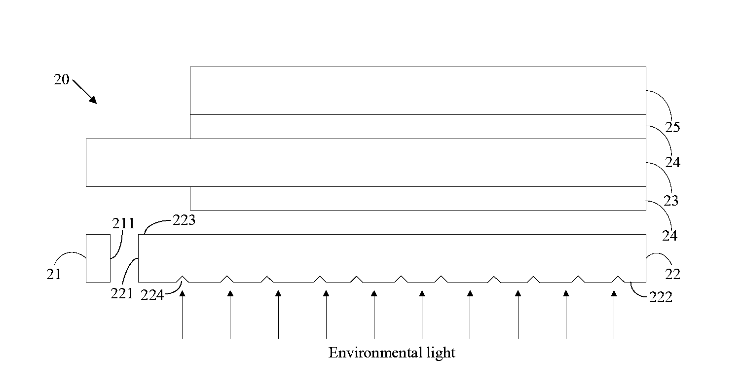
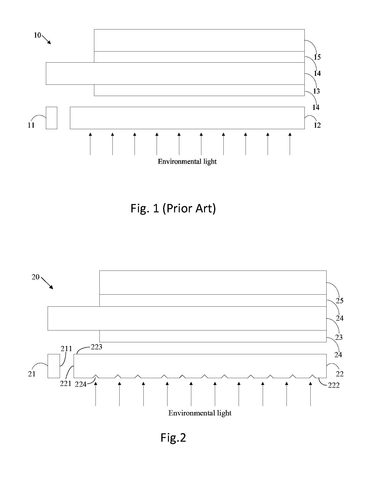
[0048]FIG. 2 is a schematic structural view of a first preferred embodiment of a transparent display device 20 of the present invention. In this preferred embodiment, a transparent display device 20 comprises a display module and a backlight module.

[0049]The display module comprises a liquid crystal display panel 23, polarizers 24 and an optical thin film 25. The liquid crystal dis...


PUM


Abstract

A transparent display device is provided herein, which comprises a display module and a backlight module. The display module includes a liquid crystal display panel, polarizers and an optical film. The backlight module includes a light source and a light guide plate, wherein the light guide plate includes a first light incident plane, a second light incident plane and a light emitting plane. The first light incident plane is disposed opposite to a light emitting plane of the light source. A plurality of caves are disposed on the second light incident plane to enhance the environmental light. The present invention raises an incident amount of the environmental light.

Description

BACKGROUND OF THE INVENTION[0001]Field of Invention[0002]The present invention relates to a field of displays, and in particular to a transparent display device.[0003]Description of Prior Art[0004]A transparent device means that a display panel has a certain level of transparency by itself, with a capability of displaying the background of the back side of the transparent display panel, clearly. A transparent display panel is suitable for windows of buildings, cars, and shops. Apart from an original function of a transparent display, the transparent display panel has a development potential as the market focus on possibly displaying messages on the panel in the future.[0005]FIG. 1 is a schematic structural view of a prior transparent display device. The transparent display device 10 comprises a light source 11, a light guide plate 12, a transparent display panel 13, a polarizer 14, and an optical thin film 15. By external natural light to look objects behind the transparent display ...

Claims


Application Information

Patent Timeline
IPC IPC(8): F21V8/00G02F1/1335
CPCG02B6/0016G02F1/133528G02F2001/133618G02B6/0068G02B6/0023G02B6/0011G02F1/133615G02F1/133618G02B5/30G02B6/0031G02B6/0053G02F1/1335
Inventor HSIAO, YU-CHUNCHEN, SHIH HSIANGTANG, GUOFULI, QUANLV, CHENGLINGGUO, CHAOFAN
Owner TCL CHINA STAR OPTOELECTRONICS TECH CO LTD
Why Eureka
Try Eureka