Extendable Tang for a Firearm
a technology of extension tang and firearm, which is applied in the field of extension tang for firearm use, can solve the problems of not being very accurate at a distance, and achieve the effect of convenient construction, compactness and concealability
- Summary
- Abstract
- Description
- Claims
- Application Information
AI Technical Summary
Benefits of technology
Problems solved by technology
Method used
Image

Examples
second embodiment
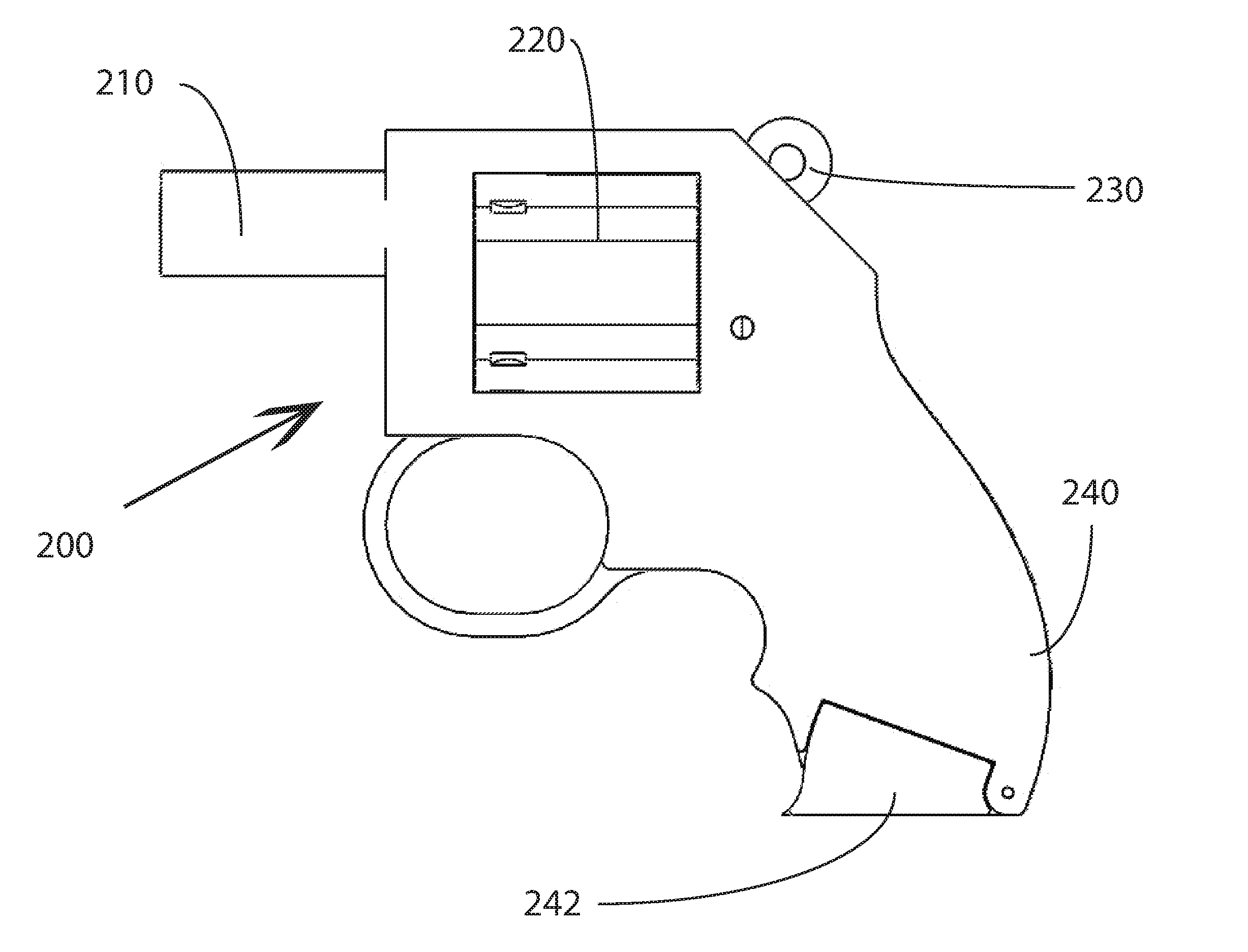
[0062]A second embodiment involves a specially shaped tang 420 with a tang extension 430 that is deployed due to direct pressure on the tang extension 430. This embodiment is shown in FIGS. 23-25. Tang 420 and tang extension 430 are hollow and surround firearm receiver 400. The tang extension 430 extends, when tang 420 stowed, past the back strap of the firearm grip 410. Grip panels 405 for firearm grip 410 each feature an arcuate channel 415 through which the tang extension 430 of the tang travels. The tang extension 430 acts as a push button that is passively depressed when the weapon is brought to bear in the user's hand. When grasping the firearm, the user's hand depresses the tang extension 430 into receiver 400 (with a provided notch), thereby forcing the tang 420 downwards. The tang 420 may be spring-biased so that holstering the firearm, or in any way unhanding it, will automatically retract the tang 420 to a stowed position.
third embodiment
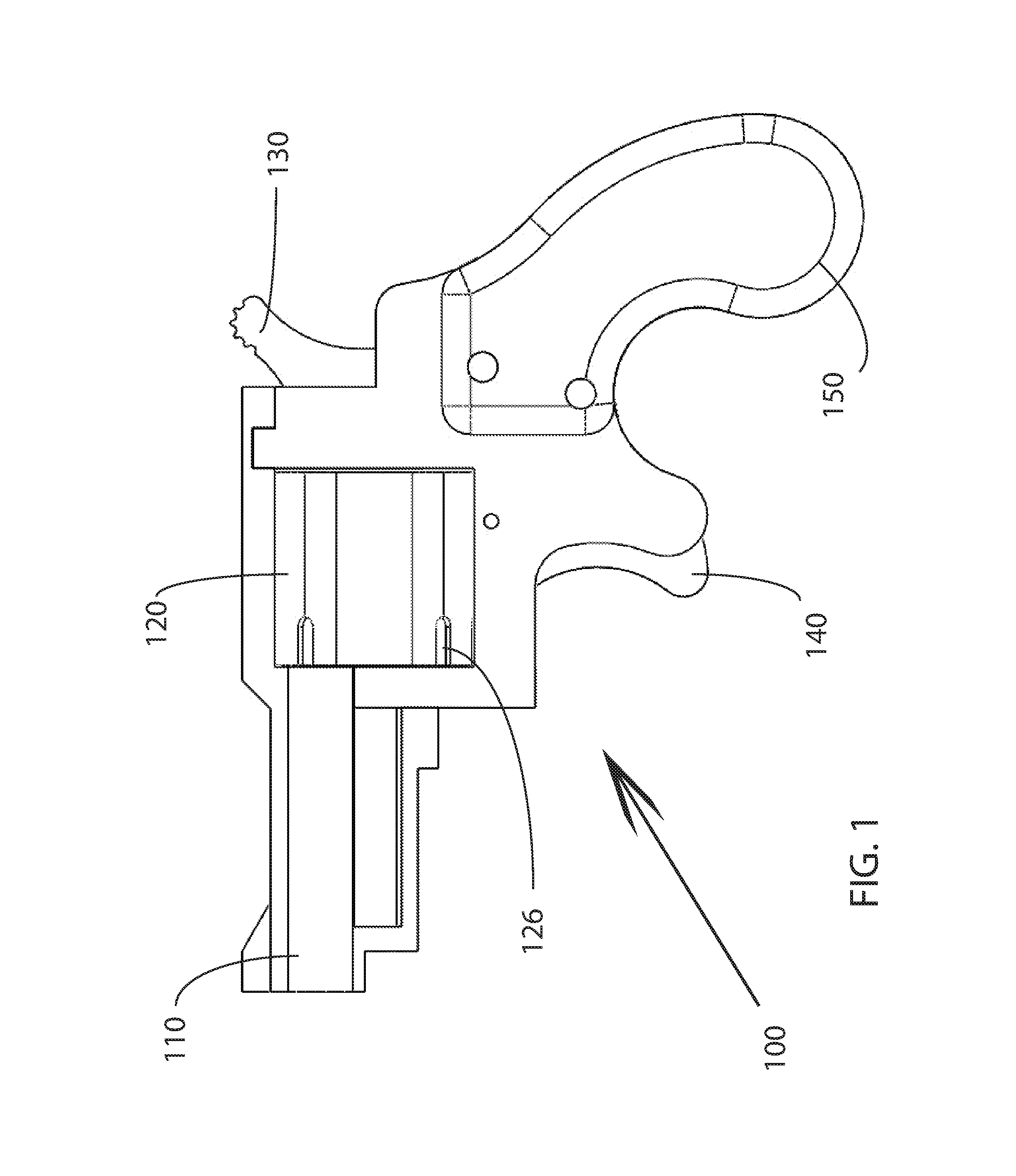
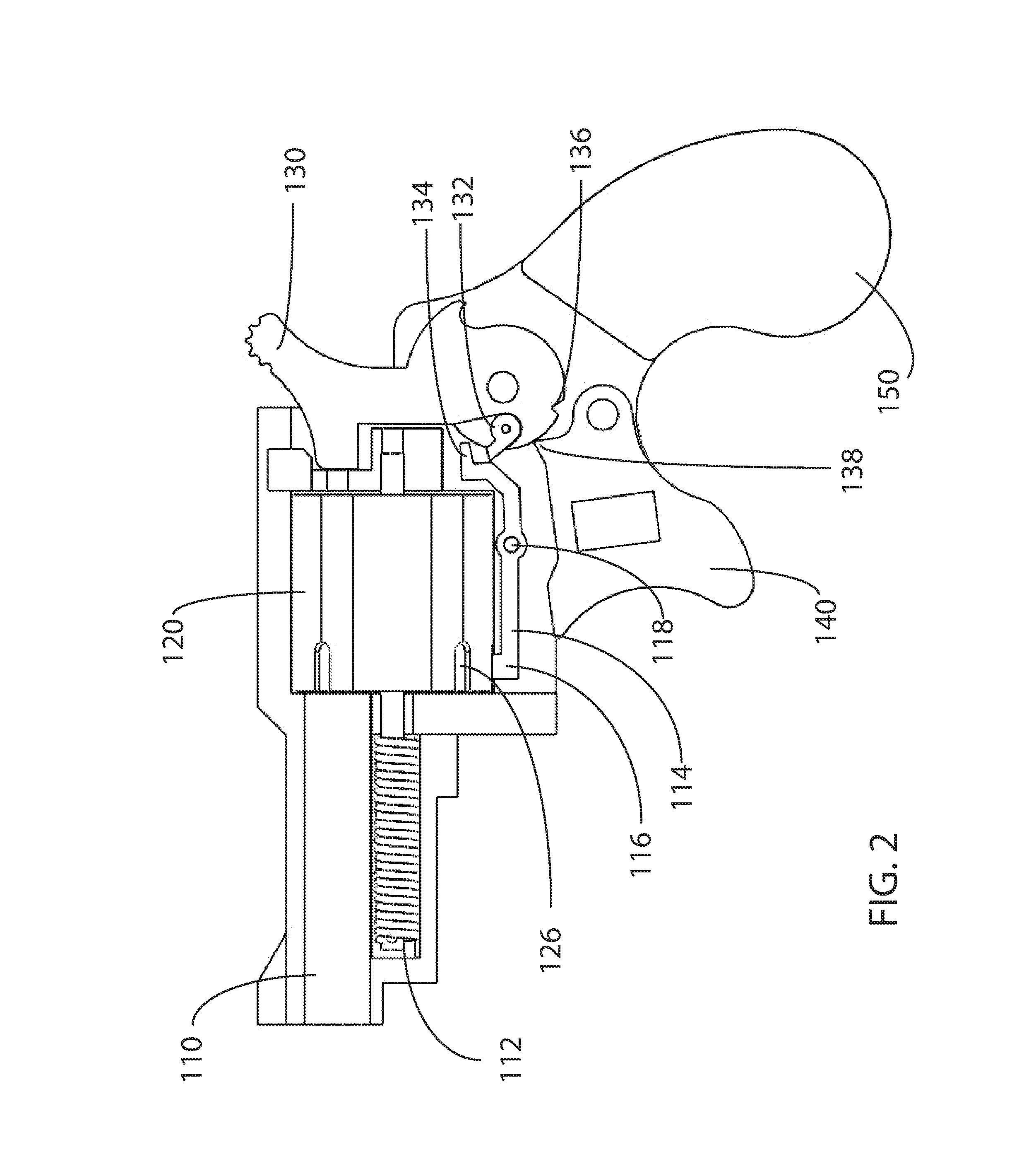
[0063]As shown in FIGS. 26-28, a third embodiment is also passively deployed, but utilizes a lever 520 so that pressure from the user grasping the firearm is indirectly applied from the user's hands to the extendible tang 530. Lever 520 protrudes from the front of grip 510 and is pivotally mounted within the grip 510, between the grip panels 507 and receiver frame 505. The location of this protruding end of the lever 520 is such that a user will automatically actuate the lever 520 when gripping the firearm 500. Grip panels 507 may provide the fulcrum for the lever and possibly channels for the tang 530. The other end of the lever is connected to the tang 530, close to its pivot point 535 on the receiver frame 505 of the firearm 500, or, alternately, on the grip panels 507. Because of its location on the tang 530, small movements of the lever 520 create arcuately significant movement of the tang 530, such that the tang 530 is fully exposed when the lever 520 is actuated by the user. ...
fifth embodiment
[0068]It should also be noted that the fifth embodiment is readily adaptable for magazine fed handguns (FIGS. 41-44), not just the revolver depicted in the initial figures. For this version of the embodiment, the lock bar 729 may have a differently shaped fork so as to comport with the shape of the grip. It nonetheless operates in the same manner.
[0069]The embodiments indicated within this specification may be utilized on any existing firearm with minimal alteration of the firearm. In some cases, the receiver frame may need to be cut in order to accommodate the mechanisms described herein. Grip panels are easily designed to incorporate the mechanisms described. Tangs and other components may be mounted either upon the firearm frame or grip panels. Firearms may also be developed and designed with the mechanisms described herein specifically in mind such that grip panels and receiver frames may be manufactured intending for the use of the present invention therewith. It is easily cons...
PUM
 Abstract
Description
Claims
Application Information
 - R&D
- Intellectual Property
- Life Sciences
- Materials
- Tech Scout
- Unparalleled Data Quality
- Higher Quality Content
- 60% Fewer Hallucinations
Browse by: Latest US Patents, China's latest patents, Technical Efficacy Thesaurus, Application Domain, Technology Topic, Popular Technical Reports.
© 2025 PatSnap. All rights reserved.Legal|Privacy policy|Modern Slavery Act Transparency Statement|Sitemap|About US| Contact US: help@patsnap.com