
Lockable smart plug

a smart plug and lockable technology, applied in the direction of power measurement by digital technique, coupling device connection, coupling device details, etc., can solve the problems of plugs not providing locking mechanisms or secure attachments, smart plugs not providing control software and plug communication

Inactive Publication Date: 2016-11-24
KUDOSO TECH LLC
View PDF4 Cites 15 Cited by
  • Summary
  • Abstract
  • Description
  • Claims
  • Application Information

AI Technical Summary

Benefits of technology

The present invention is related to a smart plug which has a housing unit, at least one electrical contact on the housing unit, at least one electrical receptacle, and a cover for closing over the receptacle. The smart plug also includes a locking mechanism to secure the cover and a measuring device to monitor usage of the receptacle. The cover can have an opening to allow an electrical cord to egress. The smart plug can also have a speaker to provide an auditory warning of changes in state. The locking mechanism can include a tubular cam lock or an internal electromagnetic lock. In another embodiment, the smart plug has two independently monitored and controlled electrical receptacles. The invention also includes current sensing metrology electronics connected to the smart plug controller for monitoring usage and identifying a remote electronic device plugged in. A locking band and wall divider can prevent a member from being removed once it is inserted into an electrical receptacle. The smart plug can have one or more U-shaped openings over the receptacle or multiple receptacles can be monitored. The housing unit can also have a slot for inserting the wall divider.

Problems solved by technology

However, a user cannot securely pair a smart plug with an electronic device to ensure control of that device; existing smart plugs do not provide locking mechanisms or secure attachments that prevent a power cord of a remote electronic device from being removed from the smart plug.
For example, existing smart plugs allow a person to simply remove the power cord and place it in a standard, uncontrolled power receptacle.
That is, the existing smart plugs do not secure the communication between the controlling software and the plug.

Method used


Image

  • Lockable smart plug
  • Lockable smart plug
  • Lockable smart plug

Examples


Embodiment Construction

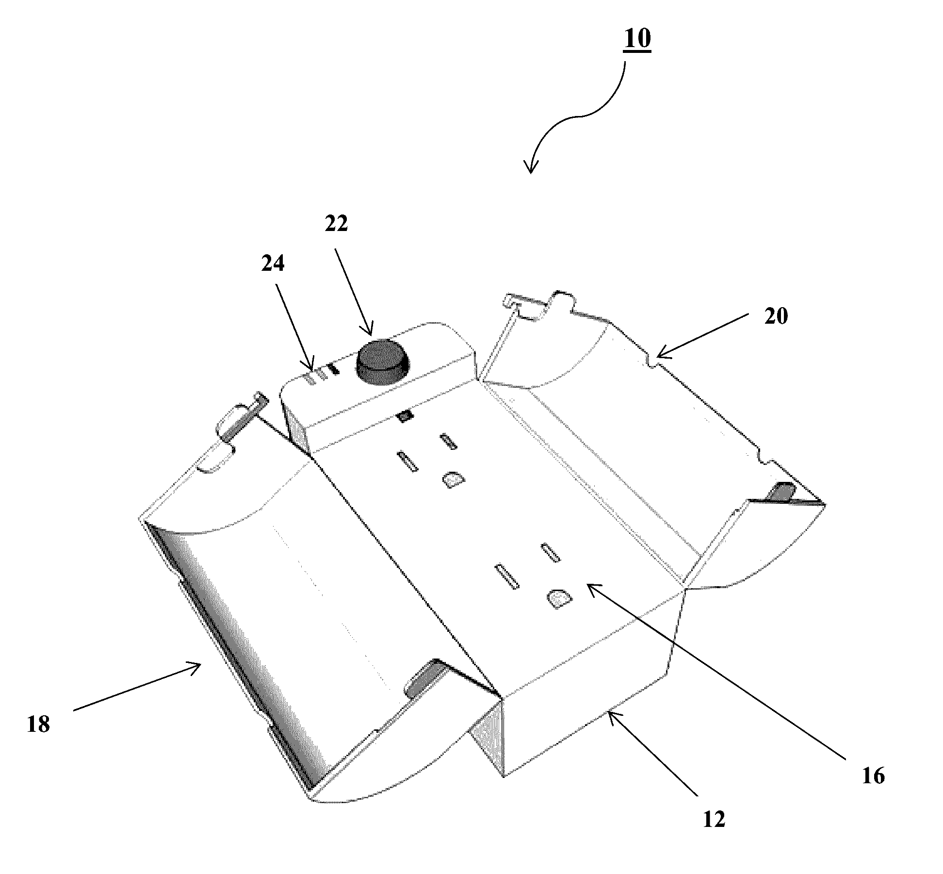
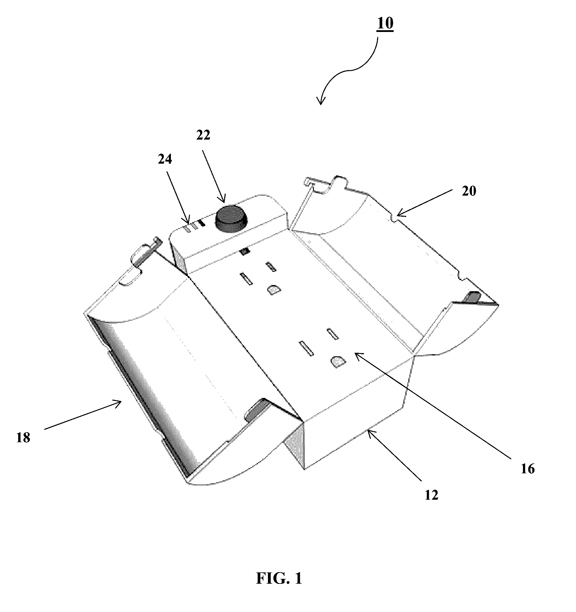
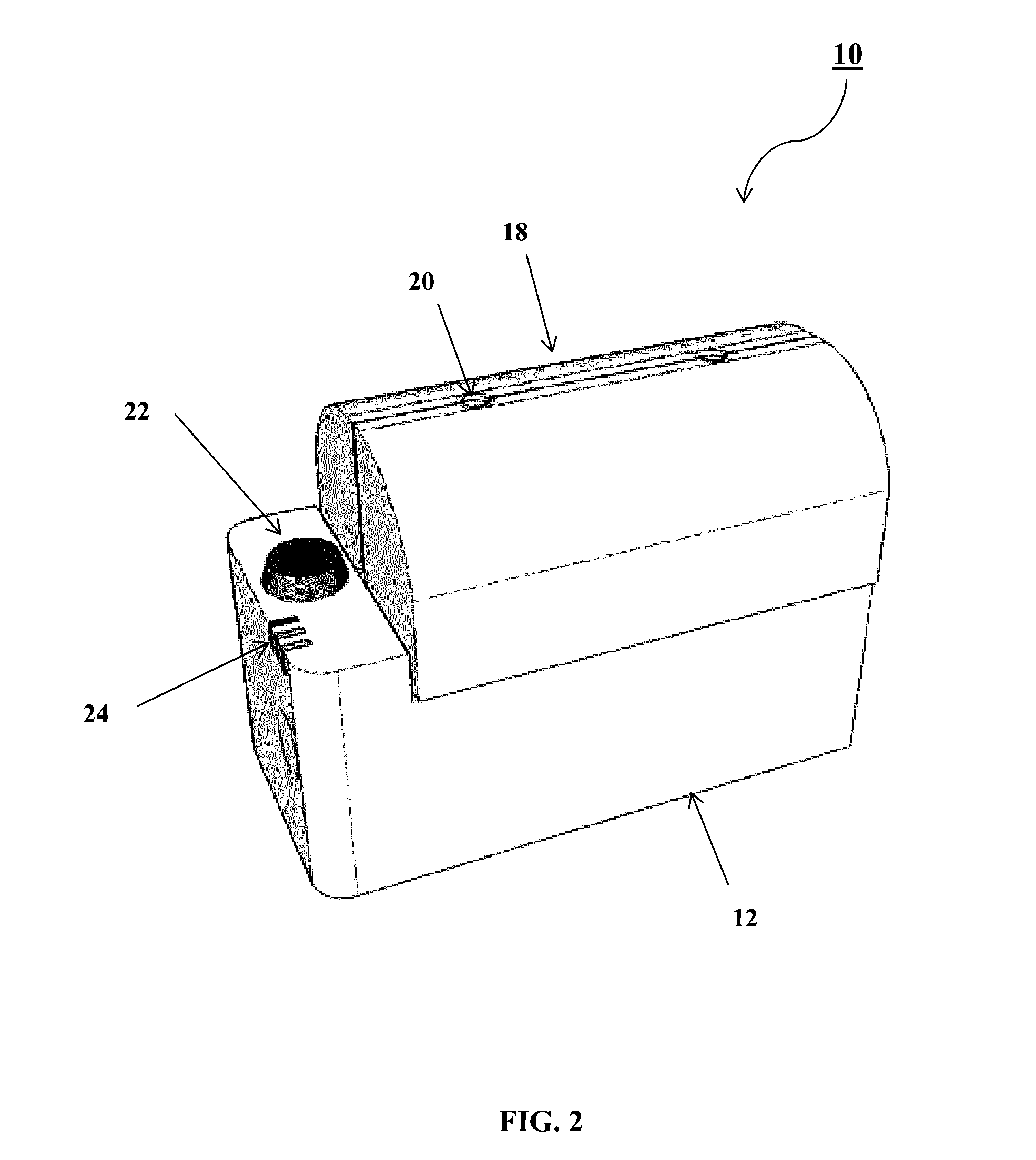
[0019]One advantage of the lockable smart plug included in the present invention is that it allows an electronic device to be monitored and controlled like a “smart” device for the purpose of monitoring and controlling usage. In particular, one aspect of the present invention allows a user to monitor and control access to certain electronic devices plugged into the lockable smart plug based on variable authorization criteria. One embodiment of the lockable smart plug of the present invention securely holds the input power cord of the electronic device inside of the smart plug's housing, and prevents unauthorized users from tampering with, removing, or gaining access to the plug of the electronic device and subsequently ensures that the electronic device will only receive power when it is authorized to do so.

[0020]For instance, if a parent wishes to ensure that their child can only use a device, e.g., video game console, television, etc., for a limited period of time, the smart plug ...


PUM


Abstract

The present invention is directed to a lockable, wireless (Wi-Fi or Bluetooth) enabled smart plug for monitoring and controlling usage of electronic devices. The smart plug of the present invention includes a housing unit, an electrical contact on a rear surface of the housing unit, an electrical receptacle on the surface opposite that of the electrical contact, and a cover configured to close over the electrical receptacle. Also included is a locking mechanism configured to secure the cover to the housing unit, a measuring device configured to monitor usage of the electrical receptacle, and a secure communication protocol to control the unit remotely.

Description

FIELD OF THE INVENTION[0001]The present invention generally relates to a device for monitoring and controlling power to electronic devices. In particular, one embodiment of the present invention includes a secure, lockable, wireless (Wi-Fi or Bluetooth) enabled smart plug for monitoring and controlling usage of electronic devices.BACKGROUND OF THE INVENTION[0002]There are a number of different smart plugs on the market today that control electrical power through the plug via software. However, a user cannot securely pair a smart plug with an electronic device to ensure control of that device; existing smart plugs do not provide locking mechanisms or secure attachments that prevent a power cord of a remote electronic device from being removed from the smart plug. For example, existing smart plugs allow a person to simply remove the power cord and place it in a standard, uncontrolled power receptacle. In addition, existing smart plugs are essentially open devices. That is, the existin...

Claims


Application Information

Patent Timeline
IPC IPC(8): H01R13/639H01R13/66G01R21/133H01R25/00
CPCH01R13/6395G01R21/133H01R13/6683H01R25/006H01R13/6397H01R31/065H02J7/0044H02J7/00
Inventor KAZMIER, MICHAEL STEVEN
Owner KUDOSO TECH LLC
Learn More