Eureka AIR delivers breakthrough ideas for toughest innovation challenges, trusted by R&D personnel around the world.

Comfortable distributed LED lighting

a distributed led lighting and comfort technology, applied in the field of distributed led lighting, can solve the problems of insufficient efficiency, intensity and/or glare, unsatisfactory glare, and discomfort for road users, and achieve the effects of low overall illuminance level, low local gradient of luminance, and low efficiency

Active Publication Date: 2016-11-24
SIGNIFY HLDG BV
View PDF0 Cites 4 Cited by
  • Summary
  • Abstract
  • Description
  • Claims
  • Application Information

AI Technical Summary

Benefits of technology

The present invention provides a lighting system that can provide strong lighting without causing glare to a person on a surface. This is beneficial for a person who is moving or in a transport vehicle and can increase safety and experience. The invention uses a lighting unit or lamp that has LED lights placed at a small distance from each other, which reduces the pitch of the LED lights. This change in pitch will decrease discomfort glare perception as it is the main factor that determines the size of the afterimage. By reducing the size of the light emitting surface, the discomfort glare will also be reduced. Additionally, the invention allows for a smaller Light Emitting Surface (LES) which can increase the luminous emittance, while keeping the total flux and the number of LEDs equal.

Problems solved by technology

It surprisingly appeared that e.g. a rectangular grid of LEDs, each with its own collimator, and having a pitch around 25 mm do not provide sufficient results in terms of efficiency, intensity and / or glare.
When high to medium power LEDs are used in these systems on the one hand intensity might be obtained, but on the other hand glare appears unsatisfactory.
An issue with these luminaires is that e.g. road users, both car drivers and pedestrians, experience discomfort glare.
Discomfort glare has been known for a long time already and also ‘conventional’ light sources can cause considerable discomfort glare.

Method used


Image

  • Comfortable distributed LED lighting
  • Comfortable distributed LED lighting
  • Comfortable distributed LED lighting

Examples


Embodiment Construction

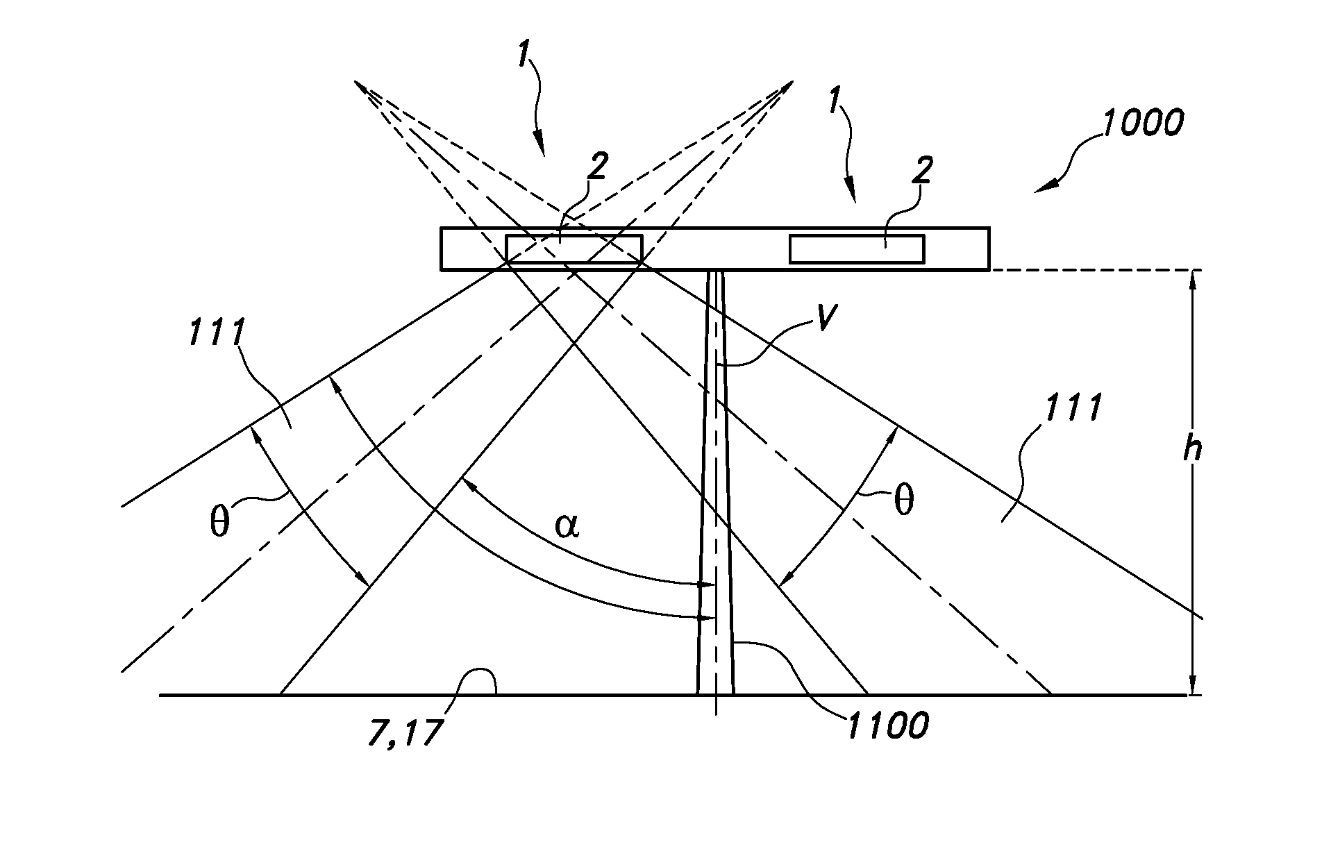
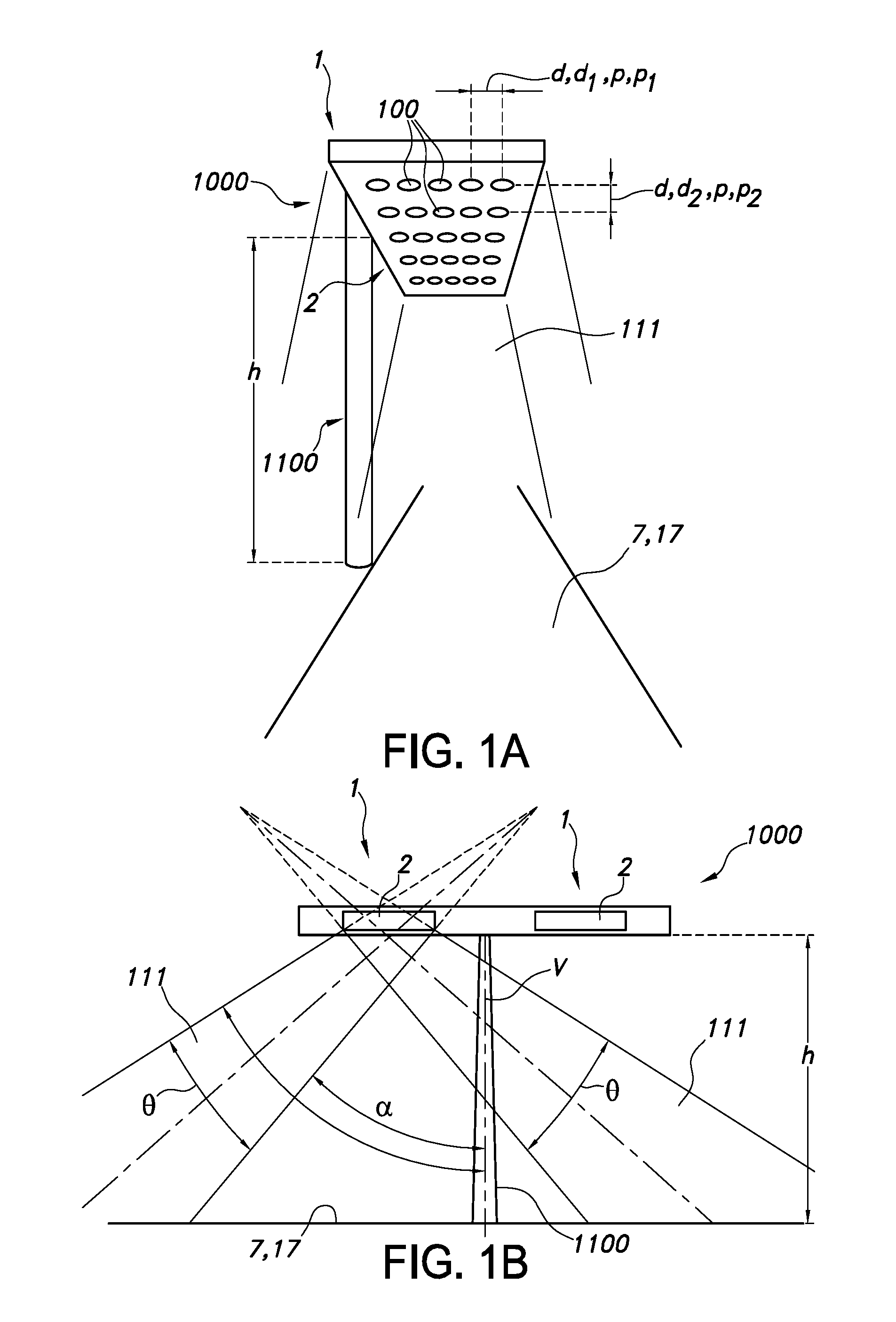
[0056]FIG. 1a schematically depicts an embodiment of a lamp 1000 comprising a lighting system 1, wherein the lamp 1000 further comprises a positioning element 1100 configured to position the lighting system 1 at a distance, here height h, of e.g. at least 3.5 m, from a surface 7 to be illuminated. Surface 7 is in this embodiment a road 17. As the lighting system 1 comprises a regular grid 2 of lighting units 100, the center-to-center distances d are the same as the pitch p. In principle, there may be two (or more) center-to-center distances d, and thus pitches p. This is indicated with d1,d2 and p1,p2, respectively. In a regular cubic arrangement, d1=d2=p1=p2=d=p. The light generated by the lighting units 100 together provides the lighting system light 111. This light may be used to illuminate the surface 7.

[0057]FIG. 1b schematically depicts a further embodiment, now in side view, of a lamp 1000. Here by way of example the lamp comprises (at least) two lighting systems 1, each havi...


PUM


Abstract

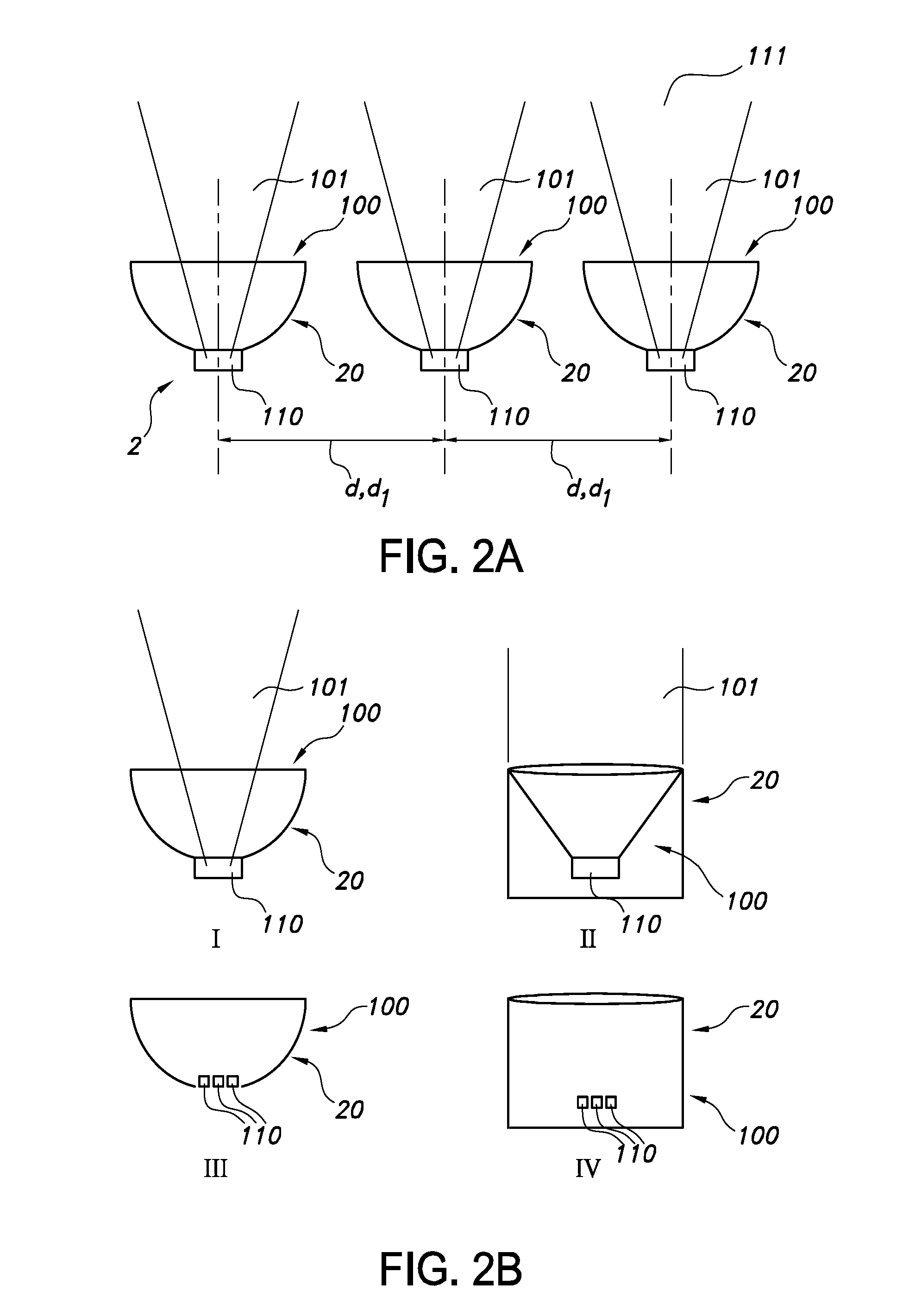
The invention provides a lighting system (1) comprising at least 16 lighting units (100) arranged in a grid (2) with in at least one direction center-to-center distances (d) between nearest neighbor lighting units (100) in the range of 4-16 mm, wherein each lighting unit (100) comprises a light source (110) and an optical element (20) configured to control a beam shape of light (101) generated by the light source (110), wherein each lighting unit (100) is conjured to generate said light (101) having a luminous flux of at least 100 lm and wherein the lighting system comprises as one luminous surface a plurality of grids (2), wherein between two nearest neighbor grids (2) an intermediate region (300) without a lighting unit (100) is configured, and with in at least one direction a shortest distance (d3) between nearest neighbor grids (2) of at least 35 mm.

Description

FIELD OF THE INVENTION[0001]The invention relates to a lighting system comprising a plurality of lighting units. The invention further relates to a lamp (or lamp fixture) comprising such lighting system, as well as applications of such lighting systems or lamps.BACKGROUND OF THE INVENTION[0002]The problem of discomfort glare of lamps is known in the art. US2010117100, for instance, describes a light-emitting module which makes it difficult to sense glare and which suppresses the temperature rise of light-emitting diode chips and has a cost advantage. The light-emitting module is provided with a base body formed with a non-metallic member having a thermal conductivity of 1 W / mk or less. In the base body, a plurality of LED chips are spaced 10 to 30 mm apart from each other, and their junction temperature when they are normally lit is preferably set at 90° C. or less. A translucent sealing member covering an area between the adjacent light-emitting diode chips is provided.[0003]US2013...

Claims


Application Information

Patent Timeline
Patent Type & Authority Applications(United States)
IPC IPC(8): F21S8/08F21V5/04F21V13/04F21V7/00
CPCF21S8/086F21V7/00F21W2131/103F21V13/04F21Y2115/10F21V5/04F21Y2105/12F21Y2105/10F21S8/08
Inventor DONNERS, MAURICE ALEXANDER HUGO
Owner SIGNIFY HLDG BV
Why Eureka
Eureka Blog
Learn More