
Working fluid for heat cycle

a technology of working fluid and heat cycle, which is applied in the direction of heat exchange elements, chemistry apparatuses and processes, etc., can solve the problems that the excellent cycle performance of working fluid may not be obtained in some cases, and the global warming of the working fluid may not be achieved, so as to achieve excellent cycle performance, less influence on the ozone layer, and less influence on global warming

Active Publication Date: 2016-11-24
ASAHI GLASS CO LTD
View PDF3 Cites 56 Cited by
  • Summary
  • Abstract
  • Description
  • Claims
  • Application Information

AI Technical Summary

Benefits of technology

The present invention provides a working fluid for heat cycle that has minimal impact on the ozone layer and global warming. The working fluid also exhibits excellent cycle performance, with a low content of impurities that can affect its production. The technical effects of this invention include reduced environmental impact and improved performance.

Problems solved by technology

However, it has been pointed out that HFCs may cause global warming.
And, if such HFO-1123 containing impurities (hereinafter sometimes referred to as crude HFO-1123) is used as it is, a working fluid excellent in the cycle performance may not be obtained in some cases.

Method used


Image

  • Working fluid for heat cycle
  • Working fluid for heat cycle
  • Working fluid for heat cycle

Examples


examples

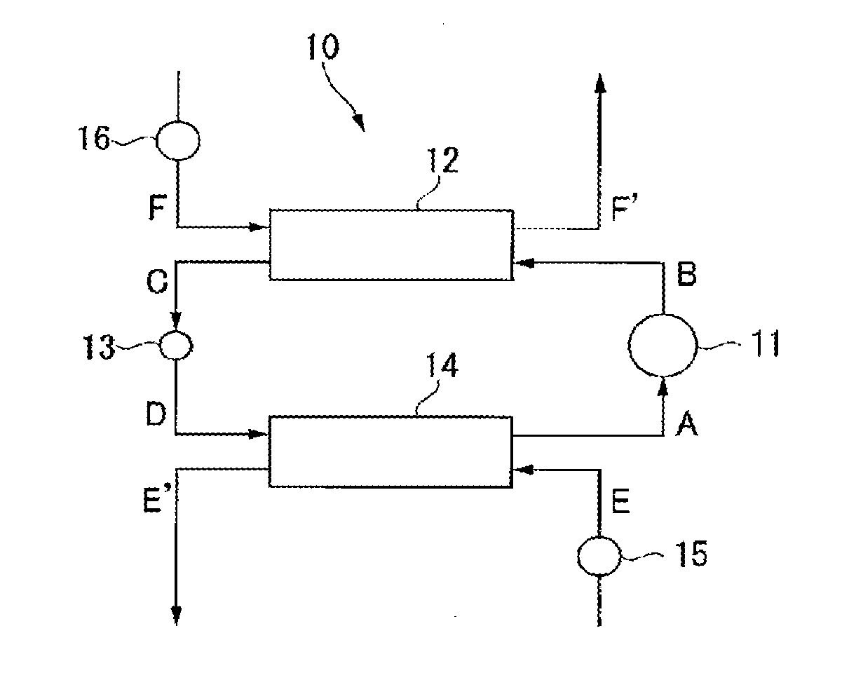
[0151]Now, the present invention will be described in further detail with reference to Examples. However, it should be understood that the present invention is by no means restricted to such specific Examples. Odd-numbered Ex. among Ex. 1 to 3 and 5 to 163 are Examples of the present invention, and even-numbered Ex. among Ex. 4 to 164 are Comparative Examples.

Ex. 1 to 164

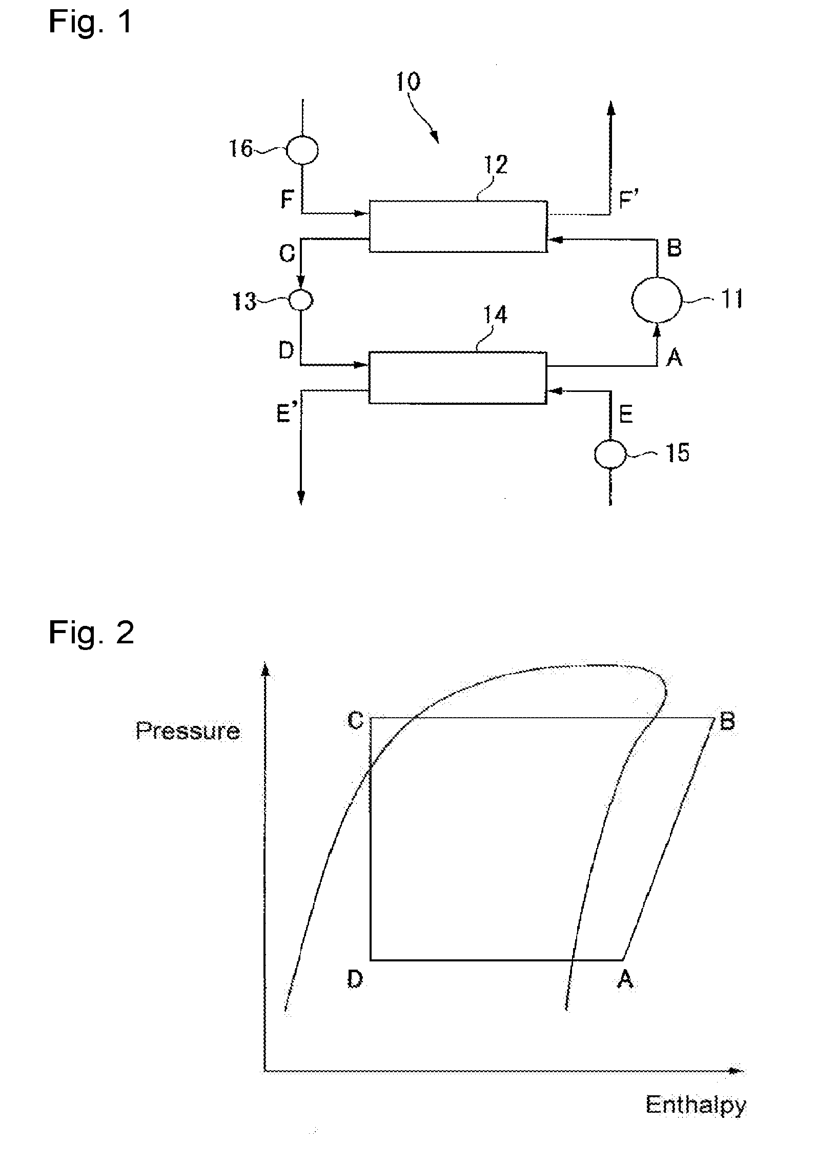
[0152]A working fluid containing HFO-1123, HFC-32 and / or HFO-1234yf, and HFO-1234ze(E) in a proportion as identified in Tables 3 to 7 and containing HFO-1132a in a proportion as identified in Table 3 based on the working fluid, was prepared. Of the working fluid, refrigerating cycle performance (hereinafter referred to as refrigerating capacity Q) was measured by the following method.

[0153]The refrigerating capacity Q means a capacity to refrigerate a load fluid, and a larger Q means that more works can be done in the same system. In other words, it means that with a working fluid having a larger Q, the desired perf...


PUM


Abstract

To provide a working fluid for heat cycle, which has less influence over the ozone layer and has less influence over global warming, and which has favorable cycle performance. A working fluid for heat cycle, which contains trifluoroethylene and difluoroethylene, wherein the proportion of the content of difluoroethylene is less than 1.5 mass % based on the working fluid.

Description

TECHNICAL FIELD[0001]The present invention relates to a working fluid for heat cycle.BACKGROUND ART[0002]Heretofore, as a working fluid for heat cycle such as a refrigerant for a refrigerator, a refrigerant for an air-conditioning apparatus, a working fluid for a power generation system (such as exhaust heat recovery power generation), a working fluid for a latent heat transport apparatus (such as a heat pipe) or a secondary cooling fluid, a chlorofluorocarbon (CFC) such as chlorotrifluoromethane (CFC-13) or dichlorodifluoromethane (CFC-12), or a hydrochlorofluorocarbon (HCFC) such as chlorodifluoromethane (HCFC-22) has been used. However, influences of CFCs and HCFCs over the ozone layer in the stratosphere have been pointed out, and their use is regulated at present.[0003]In this specification, abbreviated names of halogenated hydrocarbon compounds are described in brackets after the compound names, and in this specification, the abbreviated names are employed instead of the compo...

Claims


Application Information

Patent Timeline
IPC IPC(8): C09K5/04
CPCC09K5/045C09K2205/122C09K2205/126C09K2205/22
Inventor TASAKA, MAIFUKUSHIMA, MASATOKAWAGUCHI, SATOSHITANIGUCHI, TOMOAKITAKEUCHI, YU
Owner ASAHI GLASS CO LTD
Learn More