
Splitter terminal and connector

a technology of connectors and connectors, applied in the direction of coupling contact members, coupling device connections, electrical devices, etc., can solve the problems of relatively high insertion force and relative large connector assemblies, and achieve the effect of convenient insertion, convenient communication, and convenient communication

Inactive Publication Date: 2016-11-17
YAZAKI NORTH AMERICA
View PDF36 Cites 2 Cited by
  • Summary
  • Abstract
  • Description
  • Claims
  • Application Information

AI Technical Summary

Benefits of technology

The present disclosure provides a splitter terminal that allows for easier and more efficient connection of multiple wires. This terminal has a lower mating force compared to conventional connectors and can be packaged in a smaller space. The use of the connector assembly reduces the number of wires required and the force required for insertion. Overall, this results in a more compact and efficient connector system.

Problems solved by technology

Such a configuration results in a relatively large connector assembly and relatively high insertion forces, especially when the assembly includes a plurality of such wire pairs.
The stop surface may interfere with a surface defining the aperture to restrict removal of the terminal splitter from the first and second connector bodies.

Method used


Image

  • Splitter terminal and connector
  • Splitter terminal and connector
  • Splitter terminal and connector

Examples


Embodiment Construction

[0031]Example embodiments will now be described more fully with reference to the accompanying drawings.

[0032]Example embodiments are provided so that this disclosure will be thorough, and will fully convey the scope to those who are skilled in the art. Numerous specific details are set forth such as examples of specific components, devices, and methods, to provide a thorough understanding of embodiments of the present disclosure. It will be apparent to those skilled in the art that specific details need not be employed, that example embodiments may be embodied in many different forms and that neither should be construed to limit the scope of the disclosure. In some example embodiments, well-known processes, well-known device structures, and well-known technologies are not described in detail.

[0033]The terminology used herein is for the purpose of describing particular example embodiments only and is not intended to be limiting. As used herein, the singular forms “a,”“an,” and “the” ...


PUM


Abstract

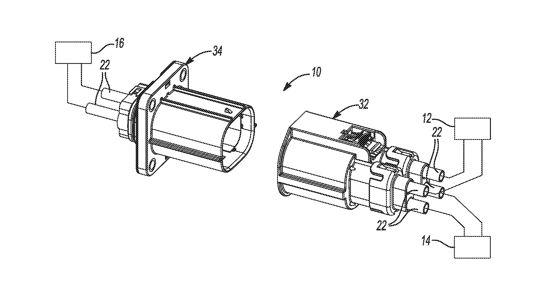
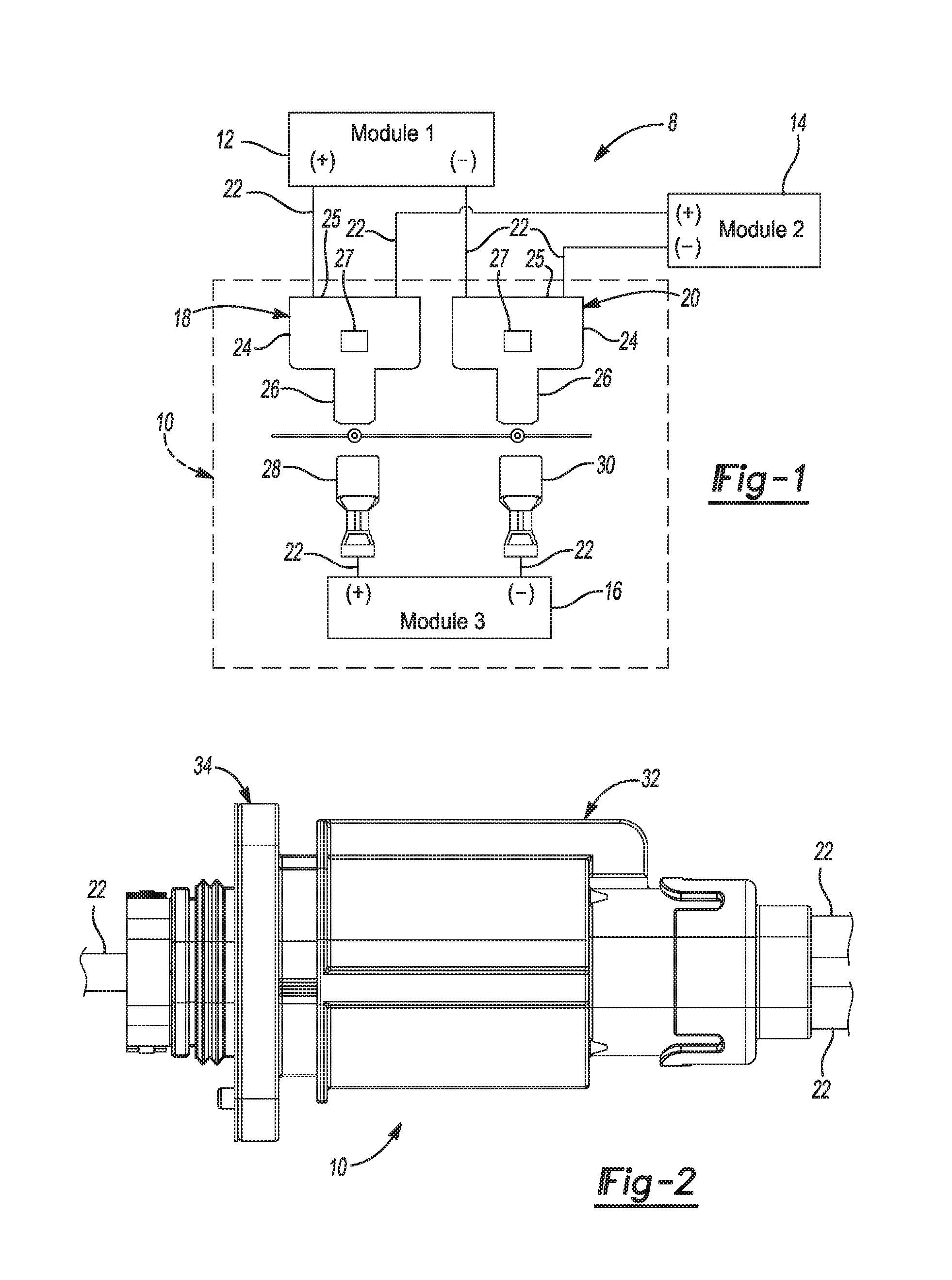
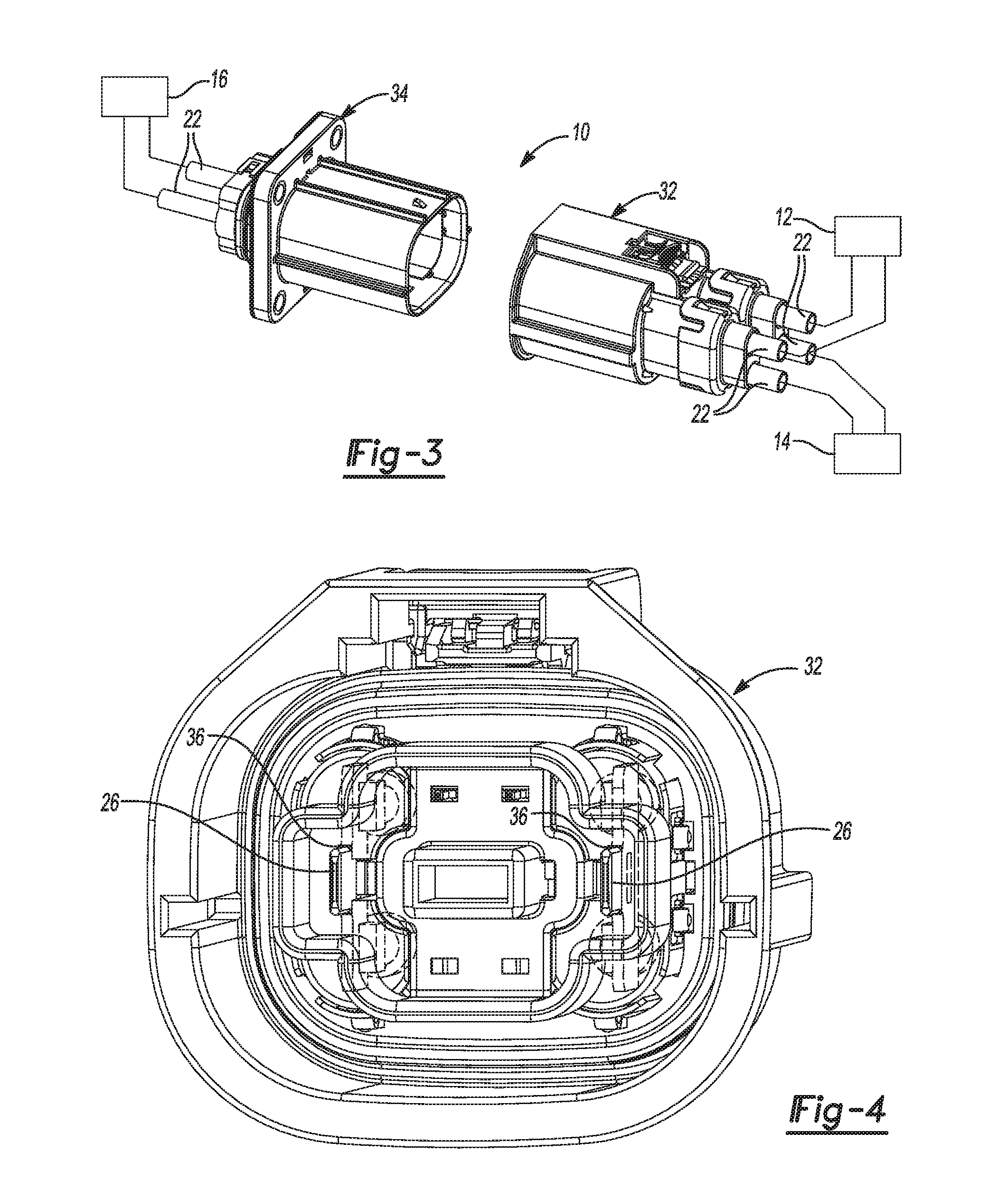
A connector assembly may include first and second connector bodies and a terminal splitter. The second connector body may matingly engage the first connector body. The terminal splitter may be received in at least one of the first and second connector bodies. The terminal splitter may include a body portion having first and second wires connected thereto and a blade portion extending from the body portion and including a third wire connected thereto.

Description

CROSS-REFERENCE TO RELATED APPLICATIONS[0001]This application claims the benefit of U.S. Provisional Application No. 62 / 162,356, filed on May 15, 2015. The entire disclosure of the above application is incorporated herein by reference.FIELD[0002]The present disclosure relates to a splitter terminal and connector assembly including the splitter terminal.BACKGROUND AND SUMMARY[0003]This section provides background information related to the present disclosure and is not necessarily prior art. This section also provides a general summary of the disclosure, and is not a comprehensive disclosure of its full scope or all of its features.[0004]An electrical connector assembly can include one or more wire pairs, each including a single male terminal crimped onto a single wire and mated with a single female terminal crimped onto another single wire. Such a configuration results in a relatively large connector assembly and relatively high insertion forces, especially when the assembly include...

Claims


Application Information

Patent Timeline
Patent Type & Authority Applications(United States)
IPC IPC(8): H01R31/02H01R13/04H01R13/10H01R13/426
CPCH01R31/02H01R13/10H01R13/04H01R13/426H01R13/4223
Inventor NG, JEN VUNAOKI, EIJIBANG, HEE JIN
Owner YAZAKI NORTH AMERICA
Learn More