
Flow passage switching unit

a switching unit and flow passage technology, applied in the direction of valve housing, valve operating means/release devices, servomotors, etc., to achieve the effect of simple structure, excellent economical use, and suppression of running costs and initial costs

Active Publication Date: 2016-11-10
SMC CORP
View PDF5 Cites 8 Cited by
  • Summary
  • Abstract
  • Description
  • Claims
  • Application Information

AI Technical Summary

Benefits of technology

The present invention provides a flow passage switching unit that can save air consumption, reduce running costs and initial costs, and has a simple structure. It is designed to move the spool to the position where the air supply port and the first output port are placed in communication, and to stop the rise in pressure of the second pressure chamber during the return stroke of the air cylinder, which blocks the introduction of compressed air into the second pressure chamber and stops the simultaneous stroke of the air cylinder. The flow passage switching unit achieves economical usage and reliably performs its working stroke.

Problems solved by technology

In addition, when the force exerted by the piston section based on the pressure of the first output port is less than the biasing force of the biasing mechanism, due to the biasing force of the biasing mechanism, the spool is moved to a second position in which the air supply port is not allowed to communicate with either of the first output port and the second output port.

Method used


Image

  • Flow passage switching unit
  • Flow passage switching unit
  • Flow passage switching unit

Examples


Embodiment Construction

[0021]A preferred embodiment of a flow passage unit and a flow passage switching unit according to the present invention will be presented and described in detail below with reference to the accompanying drawings.

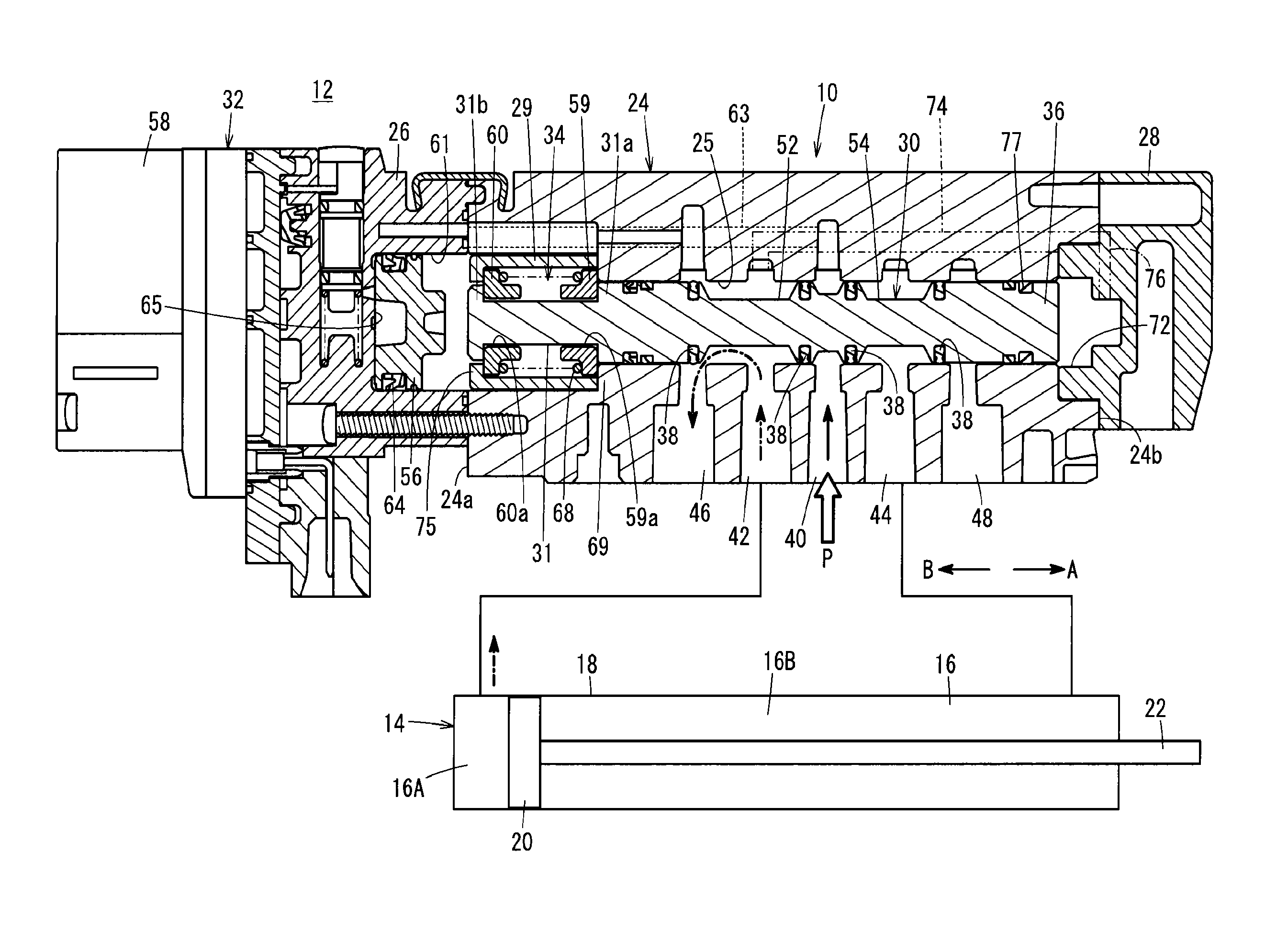
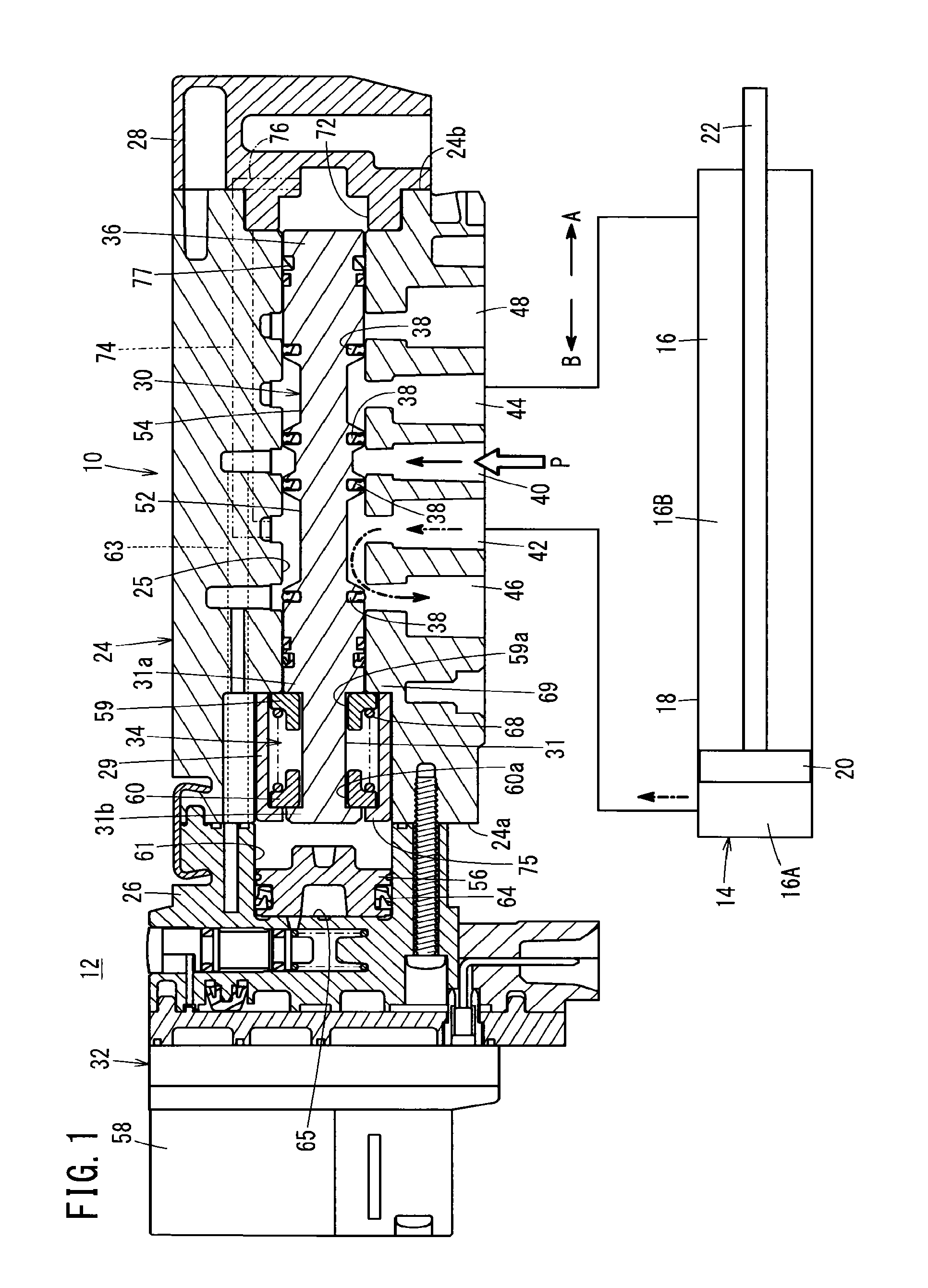
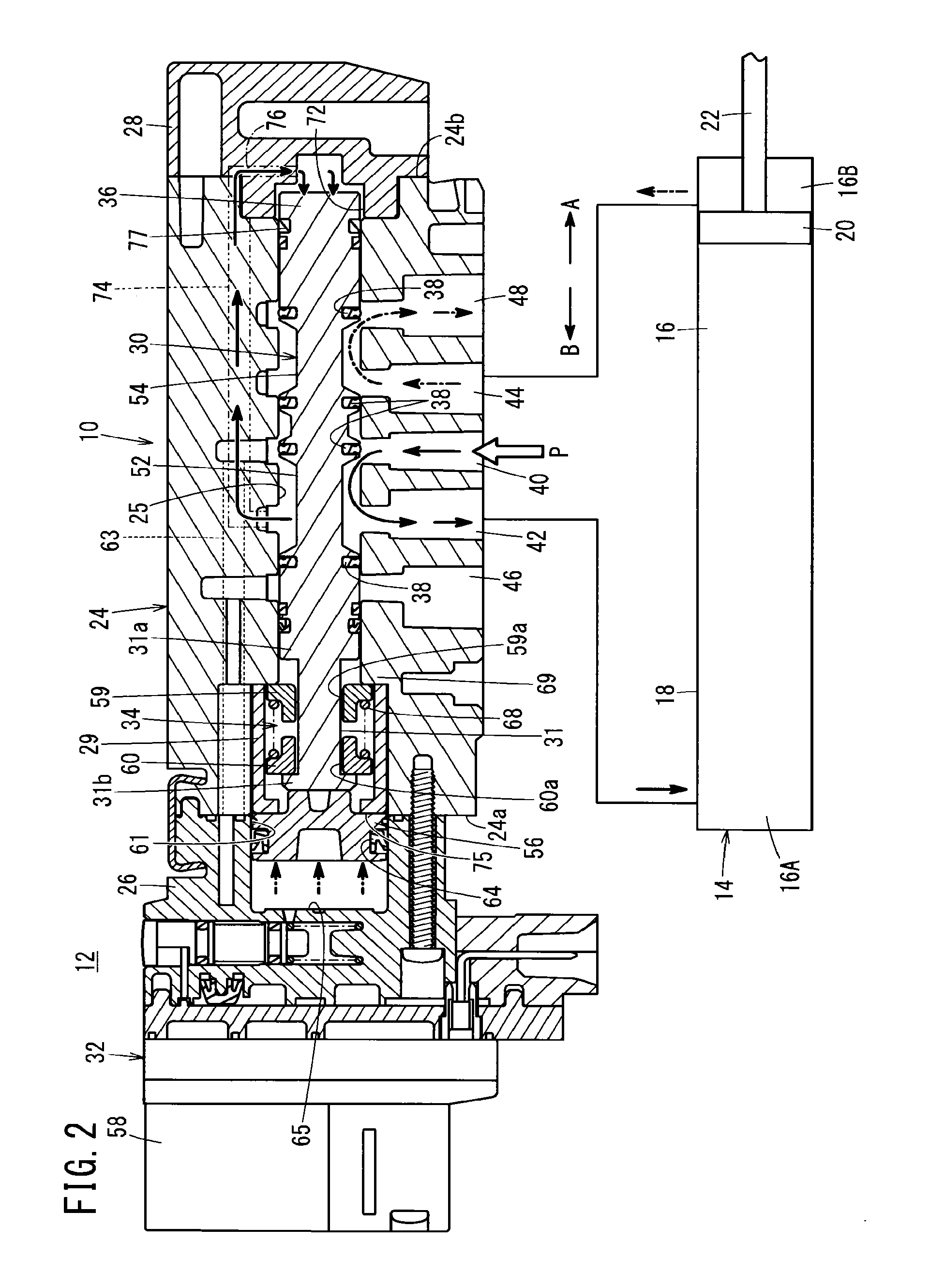
[0022]The flow passage switching unit 10 according to an embodiment of the present invention shown in FIG. 1 is used in a pneumatic system 12 equipped with an air cylinder 14. The air cylinder 14 includes a cylinder tube 18 in which a piston chamber 16 is formed, a piston 20 which is arranged for slidable reciprocal movement in the interior of the cylinder tube 18, and a piston rod 22 connected to the piston 20.

[0023]By the piston 20, the piston chamber 16 is partitioned into a first pressure chamber 16A and a second pressure chamber 16B. In the air cylinder 14, by compressed air being supplied to the first pressure chamber 16A, a working stroke is performed for effecting work, and by compressed air being supplied to the second pressure chamber 16B, a return stroke is perfo...


PUM


Abstract

A flow passage switching unit includes a valve body in which plural ports are formed, a spool arranged slidably in axial directions in the interior of the valve body, a spool drive unit for driving the spool in an A direction, a biasing mechanism that is configured to bias the spool elastically in the interior of the valve body, and a piston section that exerts a force on the spool in a B direction based on the pressure of a first output port.

Description

CROSS-REFERENCE TO RELATED APPLICATION[0001]This application is based upon and claims the benefit of priority from Japanese Patent Application No. 2015-095433 filed on May 8, 2015, the contents of which are incorporated herein by reference.BACKGROUND OF THE INVENTION[0002]1. Field of the Invention[0003]The present invention relates to a flow passage switching unit, which is used in a pneumatic system equipped with an air cylinder.[0004]2. Description of the Related Art[0005]In an air cylinder, which is widely used as a pneumatic actuator in various types of automated machinery, a piston to which a rod is fixed is moved reciprocally by supply and discharge of compressed air in respective pressure chambers thereof. Additionally, in general, supply and discharge of compressed air with respect to this type of air cylinder is carried out through a switching valve.[0006]Incidentally, in the aforementioned air cylinder, during a working stroke for performing work from among the reciprocati...

Claims


Application Information

Patent Timeline
IPC IPC(8): F16K11/07F16K31/42F16K31/124
CPCF16K11/07F16K31/426F16K31/124F16K11/0655F16K31/122F15B11/064F15B13/0402F15B13/0431F15B2211/30525F15B2211/3111F15B2211/322F15B2211/329F15B2211/7053Y10T137/86614F15B13/021F15B13/0401F16K27/04F15B2211/305
Inventor HATANO, KATSUSHI
Owner SMC CORP
Learn More