
Image mark sensing systems and methods

Active Publication Date: 2016-11-03
E IMAGE DATA
View PDF17 Cites 6 Cited by
  • Summary
  • Abstract
  • Description
  • Claims
  • Application Information

AI Technical Summary

Benefits of technology

The patent describes a method to increase the sensitivity of an area sensor. This can provide better detection and accuracy in measuring the area of a space.

Problems solved by technology

Finding the desired document(s) can represent a significant challenge of using microfilm.
However, to read this information, the film must be advanced very slowly.
Using this method to find the one document among the possible thousands would take a very long time.
Even the most experienced user wastes a great deal of time finding a desired document in this way.
If the film is not held in the correct position in the film path, these sensors can miss the IM altogether, thereby providing inaccurate results.

Method used


Image

  • Image mark sensing systems and methods
  • Image mark sensing systems and methods
  • Image mark sensing systems and methods

Examples


Embodiment Construction

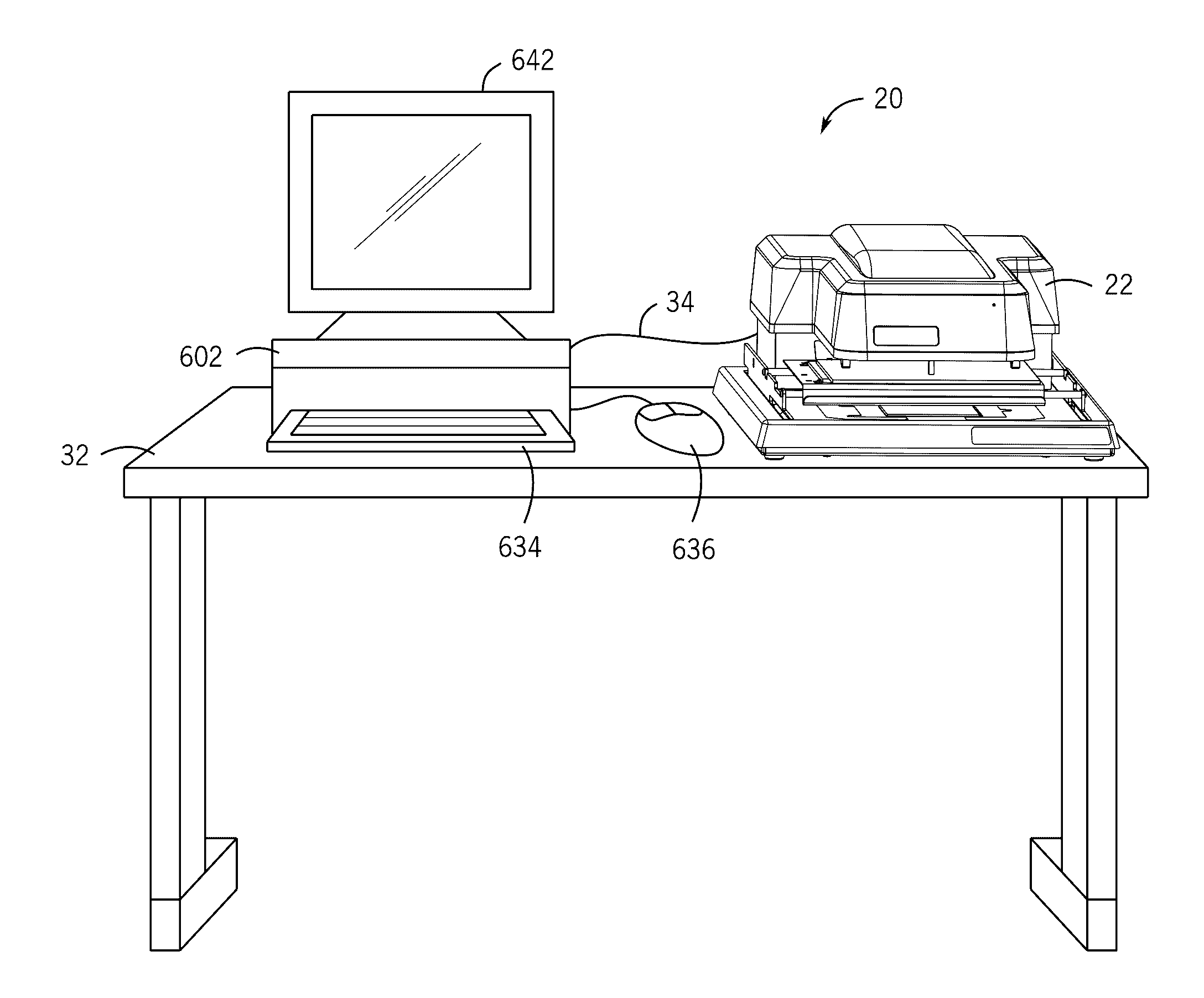
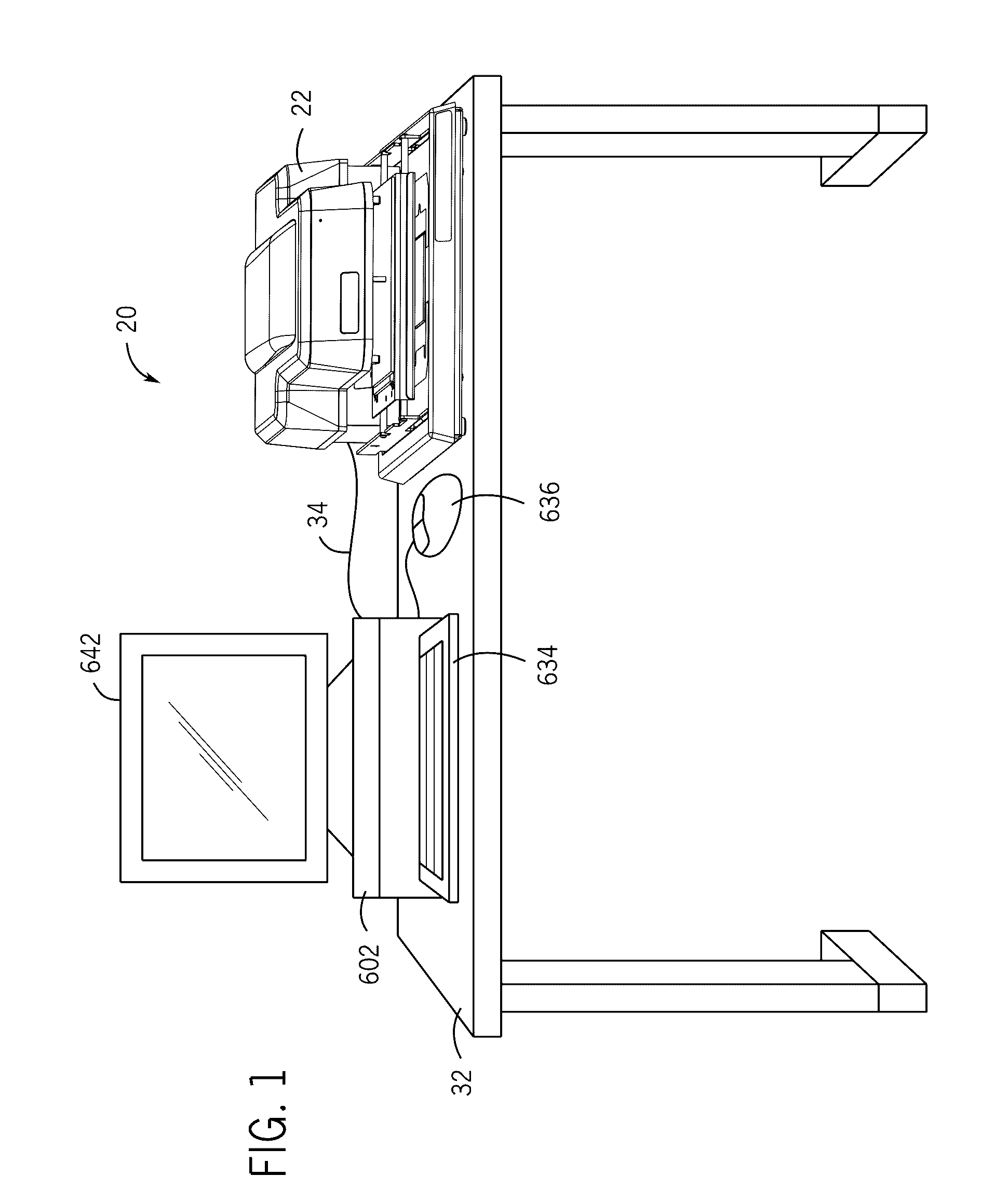
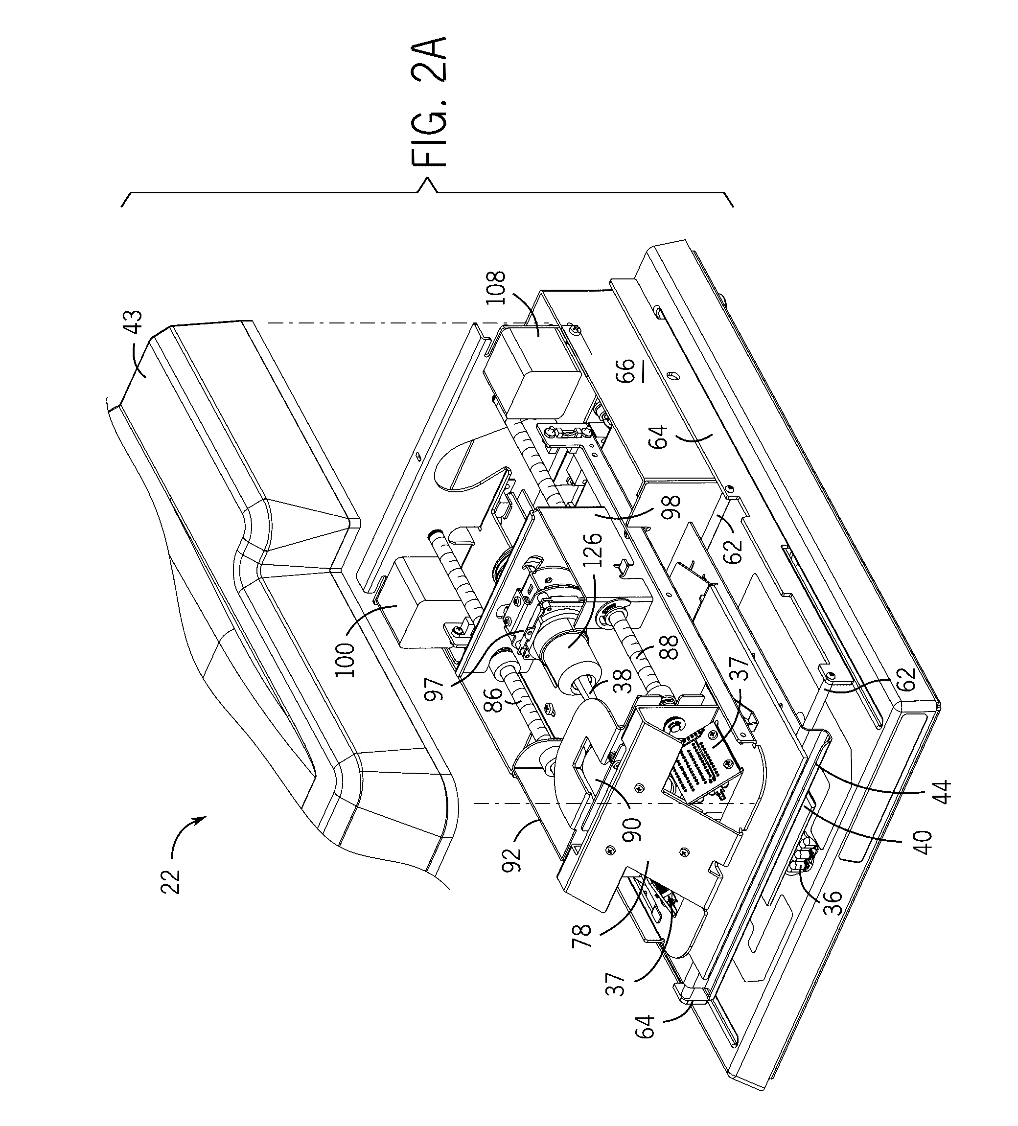
[0065]Before any embodiments of the invention are explained in detail, it is to be understood that the invention is not limited in its application to the details of construction and the arrangement of components set forth in the following description or illustrated in the following drawings. The invention is capable of other embodiments and of being practiced or of being carried out in various ways. Also, it is to be understood that the use the phraseology and terminology used herein is for the purpose of description and should not be regarded as limiting. Furthermore, the use of “right”, “left”, “front”, “back”, “upper”, “lower”, “above”, “below”, “top”, or “bottom” and variations thereof herein is for the purpose of description and should not be regarded as limiting. The use of “including,”“comprising,” or “having” and variations thereof herein is meant to encompass the items listed thereafter and equivalents thereof as well as additional items. Unless specified or limited otherwi...


PUM


Abstract

Systems and methods use a digital microform imaging apparatus for sensing an image mark on the microform containing the image of a document.

Description

CROSS-REFERENCE TO RELATED APPLICATIONS[0001]This application claims priority to and the benefit of U.S. Provisional Patent Application Ser. No. 62 / 155,280, filed Apr. 30, 2015, and entitled “Image Mark Sensing Systems and Methods,” which is hereby incorporated by reference.[0002]This application also claims priority to and the benefit of U.S. Provisional Patent Application Ser. No. 62 / 243,944, filed Oct. 20, 2015, and entitled “Image Mark Sensing Systems and Methods,” which is hereby incorporated by reference.FIELD OF THE INVENTION[0003]The present invention relates generally to using a digital microform imaging apparatus for viewing a microform containing an image of a document, and more particularly to using the microform imaging apparatus for sensing an image mark on the microform containing the image of the document.BACKGROUND OF THE INVENTION[0004]Microform images are useful in archiving a variety of documents or records by photographically reducing and recording the document ...

Claims


Application Information

Patent Timeline
IPC IPC(8): G06K9/18G03B21/11G03B21/64H04N1/00G06V30/224
CPCG06K9/183H04N1/00267H04N2201/041G03B21/64H04N2201/0081G03B21/11G06K17/0016G03B2206/00G06V30/2247
Inventor KAHLE, TODD
Owner E IMAGE DATA
Learn More