Pneumatic Tire
- Summary
- Abstract
- Description
- Claims
- Application Information
AI Technical Summary
Benefits of technology
Problems solved by technology
Method used
Image

Examples
first embodiment
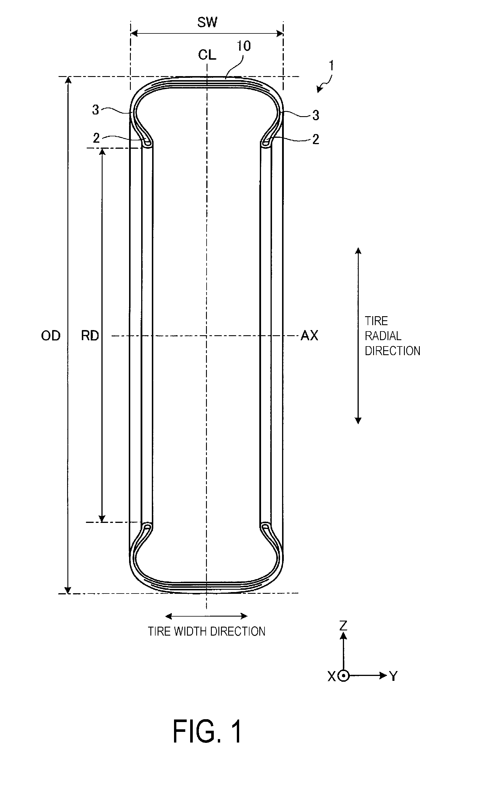
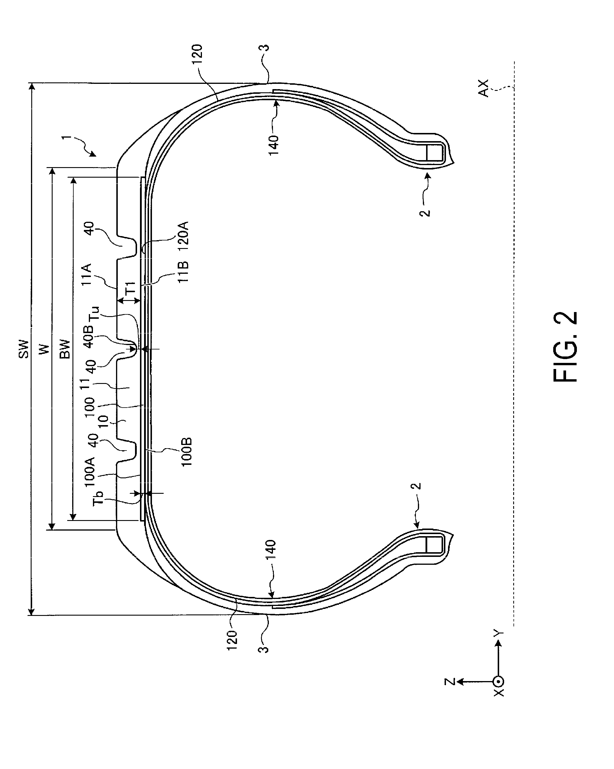
[0060]Hereinafter, a pneumatic tire 1 according to embodiments of the present technology is explained with reference to the drawings. FIG. 1 is a meridian cross-sectional view of the pneumatic tire 1 according to the embodiment of the present technology. FIG. 2 is an enlarged meridian cross-sectional view of a portion of the tire 1 according to the embodiment of the present technology. Note that the pneumatic tire 1 according to the present embodiment has a meridian cross-section shape similar to that of a conventional pneumatic tire. Here, the meridian cross-section shape of the pneumatic tire refers to the shape of the pneumatic tire in a cross section taken along a plane normal to the tire equatorial plane CL.
[0061]In the description below, an X-Y-Z Cartesian coordinates system is used, and a positional relationship of each portion is described with reference to the X-Y-Z Cartesian coordinates system. One of directions in a horizontal plane is defined as an X-axis direction, a di...
second embodiment
[0152]A second embodiment is described. In the description below, identical or substantially similar constituent portions to those of the above-described embodiment are assigned with the same reference numbers, and descriptions of those constituent portions are either simplified or omitted. In the embodiments described below, examples of the annular structure are described.
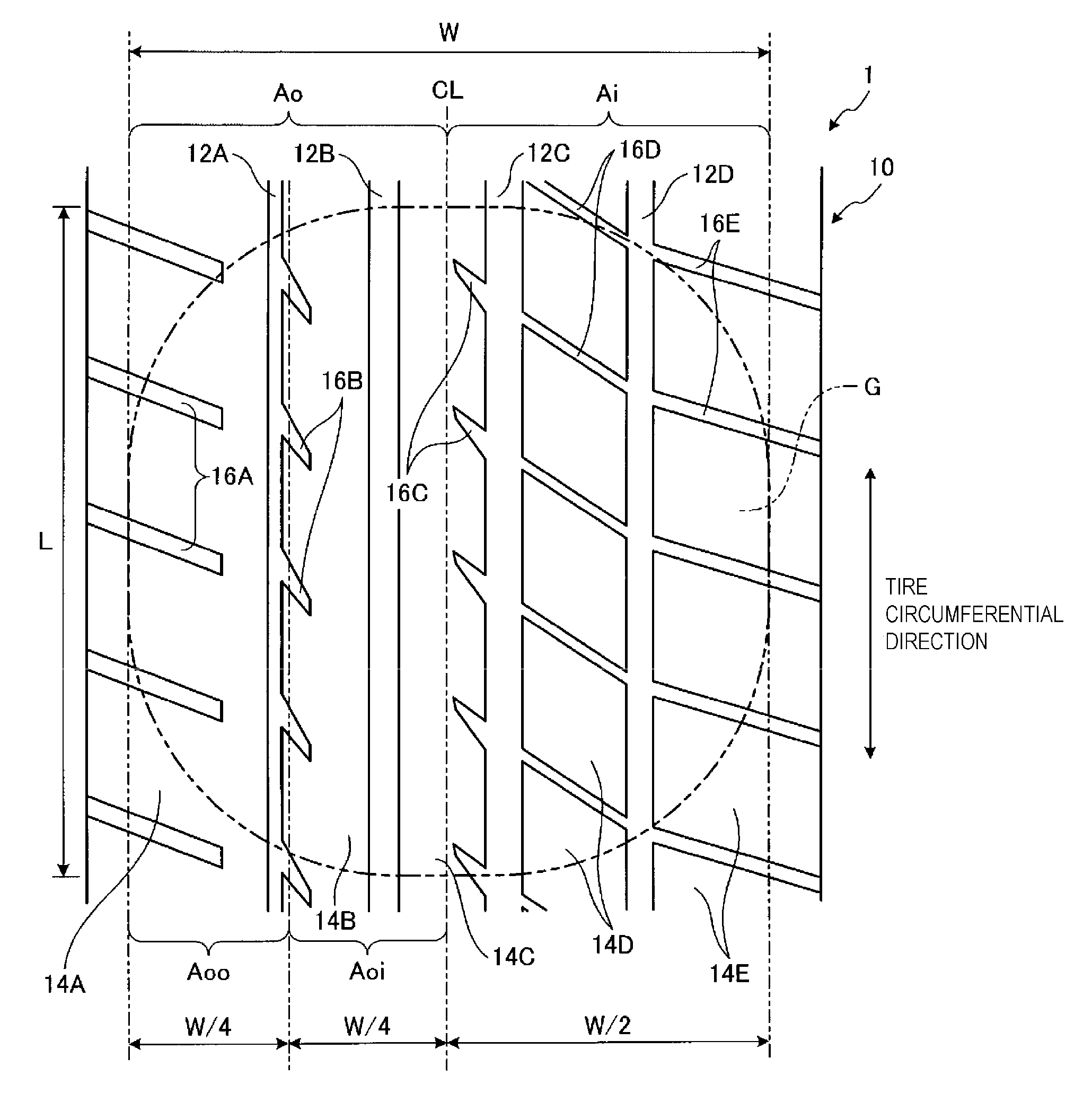
[0153]FIG. 9 is a perspective view illustrating an example of an annular structure 101 according to the present embodiment. As illustrated in FIG. 9, the annular structure 101 includes a recess and protrusion portion 50 on at least a portion of the ends in the width direction (direction parallel to the rotational axis AX) of the annular structure 101. The recess and protrusion portion 50 is provided on both sides of the annular structure 101 in the width direction. The protrusions of the recess and protrusion portion 50 are pointed. The recess and protrusion portion 50 forms a so-called saw blade shape. In the pre...
third embodiment
[0157]A third embodiment is described. FIG. 10 is a perspective view illustrating an example of an annular structure 102 according to the present embodiment. In FIG. 10, the annular structure 102 has an outer surface 102A, an inner surface 102B, and a plurality of through holes 4 that penetrate the outer surface 102A and the inner surface 102B.
[0158]In the present embodiment, the through holes 4 are disposed with an equal interval between one another in the width direction of the annular structure 102. Furthermore, the through holes 4 are disposed with an equal interval between one another in the circumferential direction of the annular structure 102. The through holes 4 are formed at an equal density in both the width direction and the circumferential direction of the annular structure 102.
[0159]In the present embodiment, at least a portion of the tread rubber layer 11, which is bonded to the outer surface 102A of the annular structure 102, can come into contact with the carcass po...
PUM
 Abstract
Description
Claims
Application Information
 - R&D
- Intellectual Property
- Life Sciences
- Materials
- Tech Scout
- Unparalleled Data Quality
- Higher Quality Content
- 60% Fewer Hallucinations
Browse by: Latest US Patents, China's latest patents, Technical Efficacy Thesaurus, Application Domain, Technology Topic, Popular Technical Reports.
© 2025 PatSnap. All rights reserved.Legal|Privacy policy|Modern Slavery Act Transparency Statement|Sitemap|About US| Contact US: help@patsnap.com