Pneumatic tire

Pending Publication Date: 2021-11-04
YOKOHAMA RUBBER CO LTD
View PDF0 Cites 1 Cited by
  • Summary
  • Abstract
  • Description
  • Claims
  • Application Information

AI Technical Summary

Benefits of technology

The present technology is about a type of tire that can reduce resistance when rolling, make it easier to keep running when flat, and make the ride more comfortable when driving under normal conditions.

Problems solved by technology

In such a run-flat tire, when the volume of a rubber that constitutes a side reinforcing layer is increased to suppress deflection under run-flat travel conditions, heat build-up is promoted and rolling resistance is increased, and there is a problem in that ride comfort under normal travel conditions deteriorates due to an increase in side rigidity.

Method used


Image

  • Pneumatic tire

Examples


examples

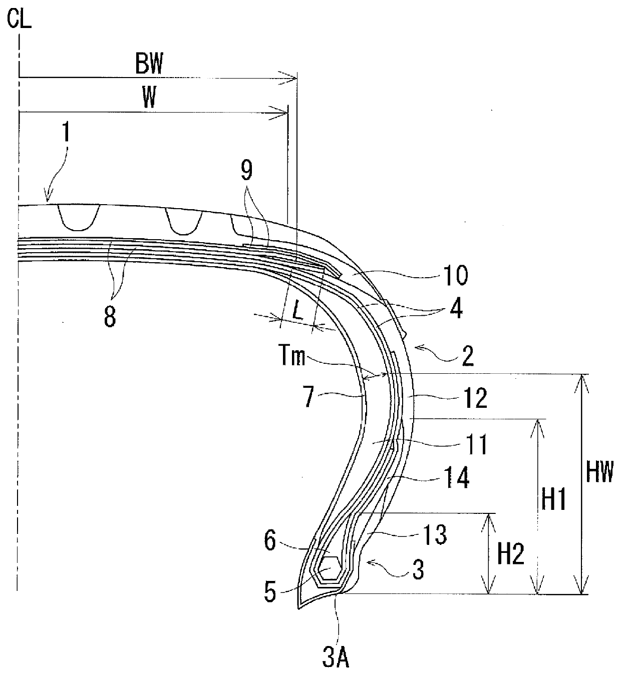
[0032]Tires of Conventional Example, Comparative Example 1 to 3, and Example 1 to 9 are manufactured, in which, in pneumatic tires having a tire size of 235 / 60RF18 and including: a tread portion having an annular shape and extending in a tire circumferential direction, a pair of sidewall portions disposed on both sides of the tread portion, and a pair of bead portions disposed on inner sides in a tire radial direction of the pair of sidewall portions, at least one carcass layer being mounted between the pair of bead portions, the carcass layer being turned up from a tire inner side to a tire outer side around a bead core of each of the bead portions, a bead filler being disposed on an outer circumferential side of the bead core in each of the bead portions, a plurality of belt layers being disposed on an outer circumferential side of the carcass layer in the tread portion, a side reinforcing layer having a crescent-shaped cross-section being disposed on the inner side in a tire widt...


PUM


Abstract

A pneumatic tire is provided. A bead filler is disposed on an outer circumferential side of each bead core in bead portions, a side reinforcing layer having a crescent-shaped cross-section is disposed on an inner side in a tire width direction of a carcass layer in a sidewall portion, and as physical properties of a rubber that constitutes the side reinforcing layer and a rubber that constitutes the bead filler, a modulus at 100% elongation is in a range from 8.4 MPa to 10.2 MPa, a tan δ at 60° C. is in a range from 0.04 to 0.08, and JIS hardness at 20° C. is in the range from 75 to 79.

Description

TECHNICAL FIELD[0001]The present technology relates to a pneumatic tire and more particularly relates to a pneumatic tire that can provide reduced rolling resistance while improving run-flat durability and can provide improved ride comfort under normal travel conditions.BACKGROUND ART[0002]In the pneumatic tires that can travel while flat, a side reinforced type run-flat tire that includes a run-flat reinforcing layer having a crescent shaped cross-section disposed on the inner surface side of the sidewall portion is known (see, for example, Japan Unexamined Patent Publication Nos. H07-304312 and 2009-061866). In such a run-flat tire, when the volume of a rubber that constitutes a side reinforcing layer is increased to suppress deflection under run-flat travel conditions, heat build-up is promoted and rolling resistance is increased, and there is a problem in that ride comfort under normal travel conditions deteriorates due to an increase in side rigidity.SUMMARY[0003]The present te...

Claims


Application Information

Patent Timeline
IPC IPC(8): B60C17/00B60C15/06B60C15/00
CPCB60C17/0009B60C15/0603B60C2009/2016B60C2017/0063B60C2015/0621B60C15/0036B60C9/2009B60C2009/2038B60C9/28B60C2017/0072B60C2015/061B60C2009/2019B60C2017/0054
Inventor TAKEMORI, RYOHEI
Owner YOKOHAMA RUBBER CO LTD
Why Eureka
Try Eureka