
Device for dynamic switching of robot control points

Inactive Publication Date: 2016-11-03
AUS DER WIESCHEN MARIA VANESSA +7
View PDF8 Cites 2 Cited by
  • Summary
  • Abstract
  • Description
  • Claims
  • Application Information

AI Technical Summary

Benefits of technology

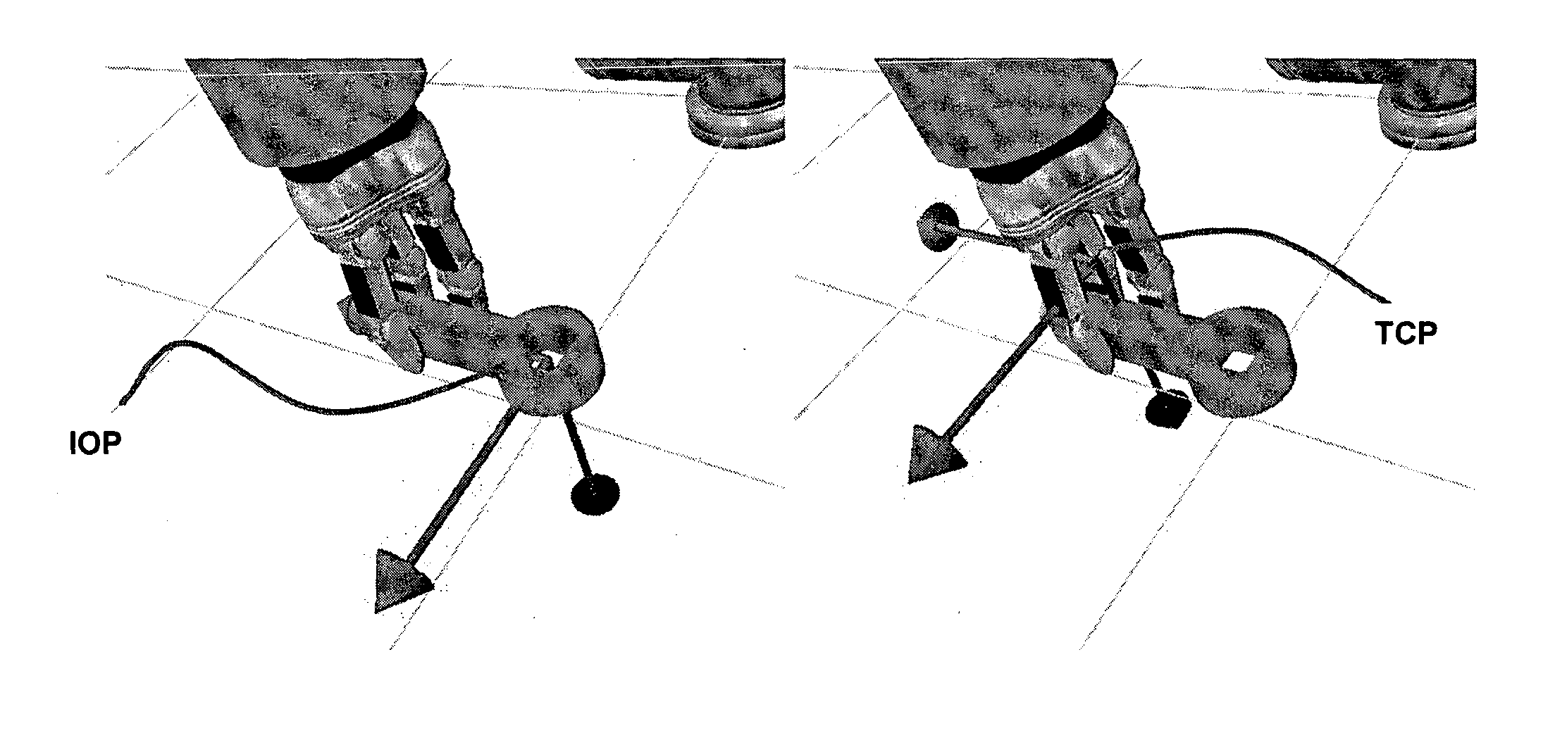
The present invention aims to improve learning by demonstration and control of an industrial robot in a teleoperative control mode. It allows the user to dynamically switch between controlling the position and orientation of the tool central point (TCP) of the robot to controlling one or more interest points of the object. The control unit dynamically switches between TCP and object interest point (OIP) in the teach mode, making use of the intuitive knowledge of the user. The switching from the TCP to OIP based teach mode results in the operator being able to control the robot movements relative to the OIP. The robot control program is determined during the teach mode, and this program is later executed during run-time mode. This ensures full predictability at runtime, while being easy to work with during teaching.

Problems solved by technology

In these production cases it can be difficult to justify implementation of a robotic system due to system programming costs.
One of the reasons for high cost is that the robot programming needs to be performed by a skilled technician.
This process is time consuming and tedious.
Since inverse kinematics of industrial robots are undetermined, the problem is often cast as an optimization problem.
However, a major problem with existing robots is that the robot control point depends on whether the arm is moved by itself, with a small object or with a long object.
For instance, the operator cannot easily teach the robot arm to move an object held by the robot arm entirely based on movements relative to the tool center point.
In case of a long object held at one end by the robot arm and intended to be moved precisely with the other end (e.g. the other end of the object has some means that should be connected precisely to something), it is extremely difficult for the operator to teach the robot arm to move the other end precisely.
Furthermore, learning how to manipulate long objects from the movements controlled at the center point is next to impossible.
One of the limitations of the current teleoperation systems is therefore that they rely on controlling a single point of interest during teaching mode.

Method used


Image

  • Device for dynamic switching of robot control points
  • Device for dynamic switching of robot control points
  • Device for dynamic switching of robot control points

Examples


Embodiment Construction

[0027]The present invention provides an intuitive and easy way to switch between control points of a robotic system. The user of the system can dynamically switch from controlling any point of the robot or the object attached to the robot. By tracking the movement of the user and transferring these movements to the robot, the system gives the user an improved and intuitive way of controlling the robot. During a robot manipulation task there will be a need to control different points of the system. Typically these points are the robot TCP and later some points on the object being manipulated. The need to switch control points appears when the robotic system grasps or manipulates an object. The device gives the user the ability to switch between these control points dynamically, allowing not only for more accurate robot control, but also serves to inform the robot on the reference point for learning from demonstration.

[0028]Involved in one embodiment of the present invention is the so...


PUM


Abstract

The invention comprises a system for switching between control points of a robotic system involving an industrial robot including a robot arm with a number of joints and provided with a tool interest point movable in a plurality of degrees of freedom.

Description

FIELD OF THE INVENTION[0001]The present invention is a device for switching between control points of a robotic system in a teleoperative control mode.BACKGROUND OF THE INVENTION[0002]There is a growing interest in applying robots in production for small or medium size production lines, where the production process needs to be adapted or modified more often. In these production cases it can be difficult to justify implementation of a robotic system due to system programming costs. One of the reasons for high cost is that the robot programming needs to be performed by a skilled technician.[0003]Recently, robot manufactures have introduced new and improved interfaces for programming robots. Such interfaces are, for instance, kinesthetic guidance or the use of a teaching pendant to control individual joints.[0004]Often when programming a robot by using one of the above mentioned interfaces, the robot operator manually moves the robot to a plurality of points along the path in order to ...

Claims


Application Information

Patent Timeline
IPC IPC(8): B25J9/16B25J19/02B25J13/08
CPCB25J9/1689B25J13/085G05B2219/40193B25J13/084B25J19/023B25J9/1687G05B2219/40144G05B2219/40154G05B2219/40155
Inventor SAVARIMUTHU, THIUSIUS RAJEETHSOELVASON, DORTHEKUKLINSKI, KAMILKRUEGER, NORBERTFISCHER, KERSTINVANESSA AUS DER WIESCHEN, MARIAKIRSTEIN, FRANZISKAMARHENKE, ILKA
Owner AUS DER WIESCHEN MARIA VANESSA
Learn More