
Side wear protection for the roller of a roller press

Inactive Publication Date: 2016-11-03
TAKRAF
View PDF4 Cites 4 Cited by
  • Summary
  • Abstract
  • Description
  • Claims
  • Application Information

AI Technical Summary

Benefits of technology

The invention reduces the amount of hard metal needed, which saves money on expenses. It also eliminates fitting problems when adding hard bodies and allows for easy dismounting of side wear protection without expensive heating of adhesive connections. The holding function of the side wear protection elements is ensured by the base body made of elastic material, which reduces the risk of breakage.

Problems solved by technology

The surfaces of the rollers are exposed to a high wear.
The lateral closure of the wear protection seems problematic.
This front surface steel shielding has the disadvantage that the hard bodies can break.
In addition, the fastening by adhesion or soldering cannot be readily separated and therefore a repair of the roller is not possible or is possible only with great difficulty.
Last but not least, the great manufacturing tolerances in structural components like hard metal result in large adhesive gaps or in significant problems in the assembly when the hard bodies have an oversize.
The large adhesive gaps are problematic since no reliable adhesion is possible and the hard bodies can fall out of the roller surface during operation.
In addition, a large amount of adhesive must be used, which is disadvantageous for the large adhesive slot.
Also, a special adhesive is required, which is disadvantageous for the adhesion of large adhesive gaps.
Excessively large hard bodies result, in addition to the problems during assembly and the associated expenses, in the risk that during the assembly fissures are produced in the hard metal bodies which can result in a subsequent failure.
Last but not least, the use of hard metal entails very high expenses.

Method used


Image

  • Side wear protection for the roller of a roller press
  • Side wear protection for the roller of a roller press
  • Side wear protection for the roller of a roller press

Examples


Embodiment Construction

[0039]The present invention is directed to, inter alfa, solving the noted deficiencies in the prior art by providing a side wear protection for the roller of a roller press that has a long service life and makes possible a simple and rapid replacement.

[0040]More particularly, in various aspects, the present invention solves the noted problems in the prior art by providing a roller for a roller press comprising a side wear protection as described herein and by a roller press as also described herein.

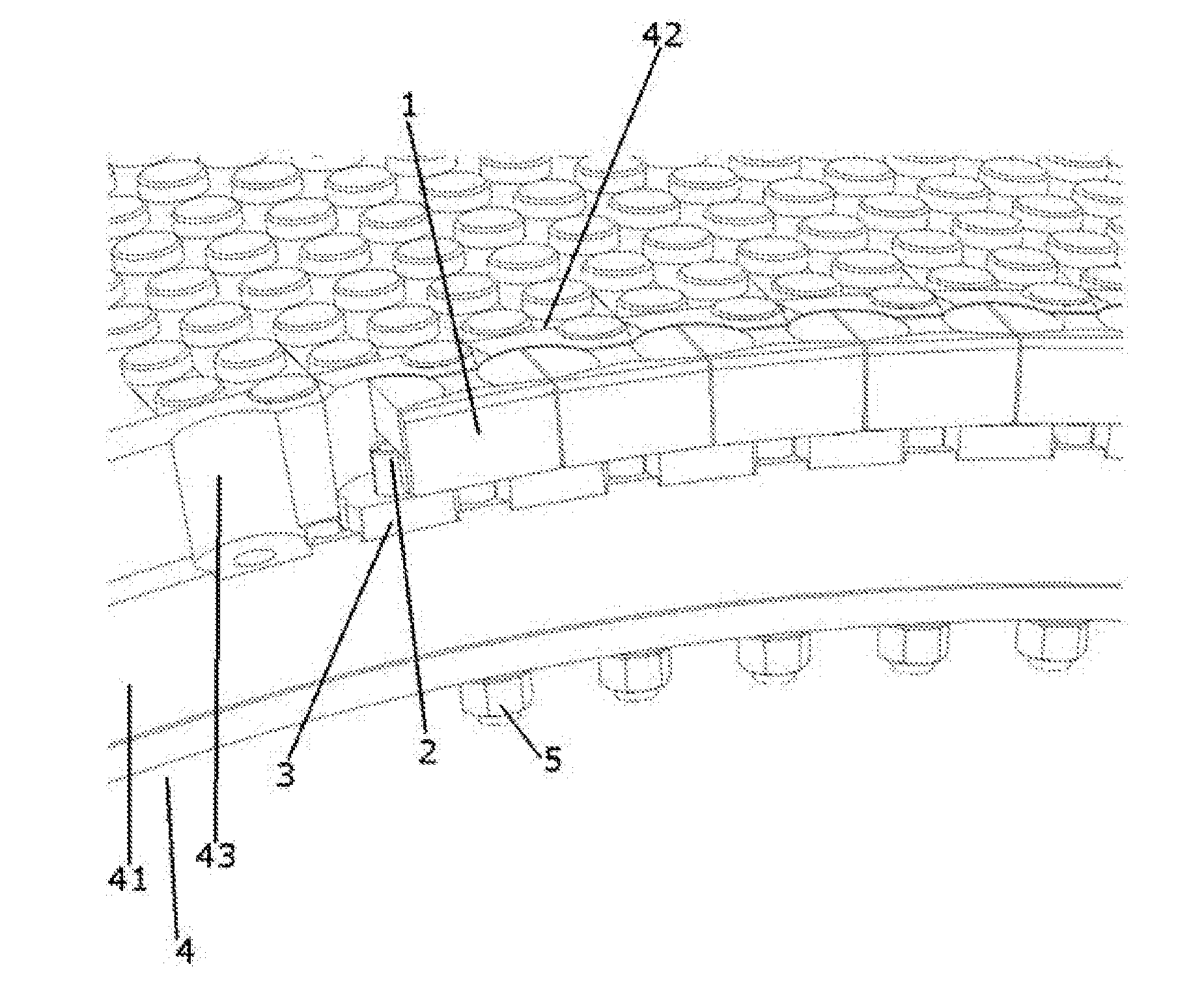
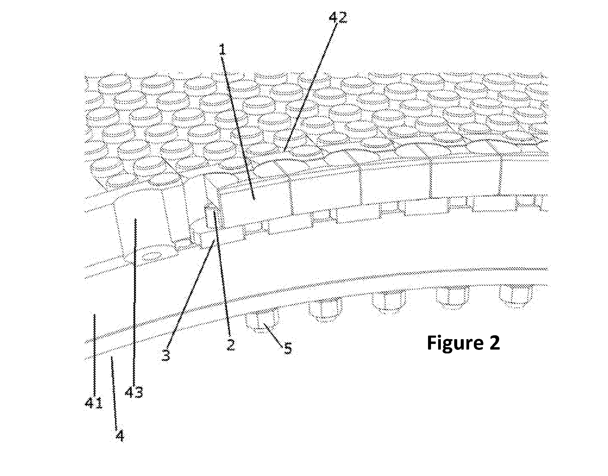
[0041]In certain embodiments, the roller in accordance with the invention for a roller press with a side wear protection comprises several side wear protection elements surrounding the roller edge. According to the invention the side wear protection elements comprise a base body of an elastic, ductile material. Furthermore, the base body comprises a threaded bolt on the base body side directed toward the roller axis.

[0042]In the following, in order to simplify the description, a definitio...


PUM


Abstract

The present invention relates to side wear protection for rollers of a roller press and to a roller of a roller press comprising this side wear protection. In one embodiment, the side wear protection according to the present invention and for the roller of a roller press comprises several side wear protection element surrounding the roller edge. According to the present invention, the side wear protection elements have a base body comprising an elastic, ductile material. Furthermore, the base body has a threaded bolt on the side of the base body directed toward the roller axis.

Description

CROSS-REFERENCE TO RELATED APPLICATIONS[0001]This application claims priority benefit under 35 U.S.C. §119 of German Patent Application No. 10 2015 207 927.9, filed Apr. 29, 2015, the entire contents of which are incorporated herein by reference.FIELD OF THE INVENTION[0002]The present invention relates to the side wear protection for rollers of a roller press and to a roller of a roller press comprising this side wear protection.BACKGROUND OF THE INVENTION[0003]Roller presses, also called high-pressure grinding rolls, comprise two rollers with the same diameter between which the material to be comminuted is introduced and forms a material bed there. A compacting takes place by the opposite rotation of the rollers and the high pressure on the material between the rollers.[0004]The surfaces of the rollers are exposed to a high wear. For this reason protective wear layers are used on the roller surface. For example, EP 0443 195 A1 suggests applying nubs of hard metal by welding on the ...

Claims


Application Information

Patent Timeline
IPC IPC(8): B02C4/30
CPCB02C2210/02B02C4/305B02C4/32B30B3/005
Inventor FRANGENBERG, MEINHARDSCHNEPPER, JORG
Owner TAKRAF
Learn More