
Hollow-fiber membrane module

Inactive Publication Date: 2016-11-03
TORAY IND INC
View PDF7 Cites 6 Cited by
  • Summary
  • Abstract
  • Description
  • Claims
  • Application Information

AI Technical Summary

Benefits of technology

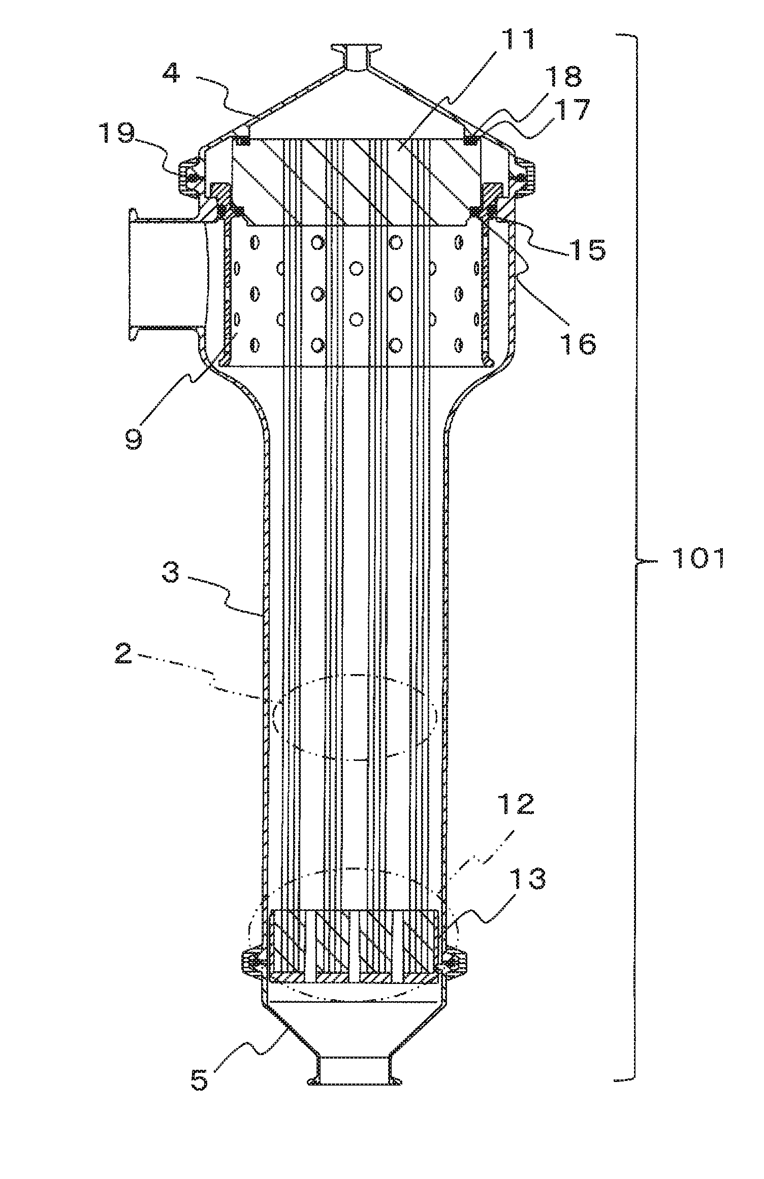
The present invention provides a hollow-fiber membrane module that can prevent an increase in pressure drop and damage to the membrane when introduced with a high flow rate of liquid or used for membrane cleaning. The module prevents contact between the membrane and the inner wall of the flow regulation cylinder, reducing the likelihood of damage.

Problems solved by technology

Similarly, there also occurred a problem of increase in the operation driving force in filtration operation or increase in the feed pressure of a cleaning liquid.
In addition, as the hollow-fiber membrane 1 follows to clog the flow regulation hole 10, there also occurred a problem of damage to the hollow-fiber membrane 1 itself.
However, in use under a severe condition that a fermentation culture or a cleaning liquid is flowed at a high flow rate, there may occur a risk that the hollow-fiber membrane at the outer peripheral part of the hollow-fiber membrane bundle would be in contact with the groove formed on the side peripheral surface of the flow regulation cylinder so that the hollow-fiber membrane would be abraded and damaged.
Further, the hollow-fiber membrane bundle 2 follows the flow of a fermentation culture that is to be a raw liquid before filtration, or follows the flow of a cleaning liquid to be lifted up to thereby augment the loosening of the hollow-fiber membrane 1, and therefore there may occur still another risk that the hollow-fiber membrane 1 would clog the flow regulation hole 10.

Method used


Image

  • Hollow-fiber membrane module
  • Hollow-fiber membrane module
  • Hollow-fiber membrane module

Examples


first embodiment

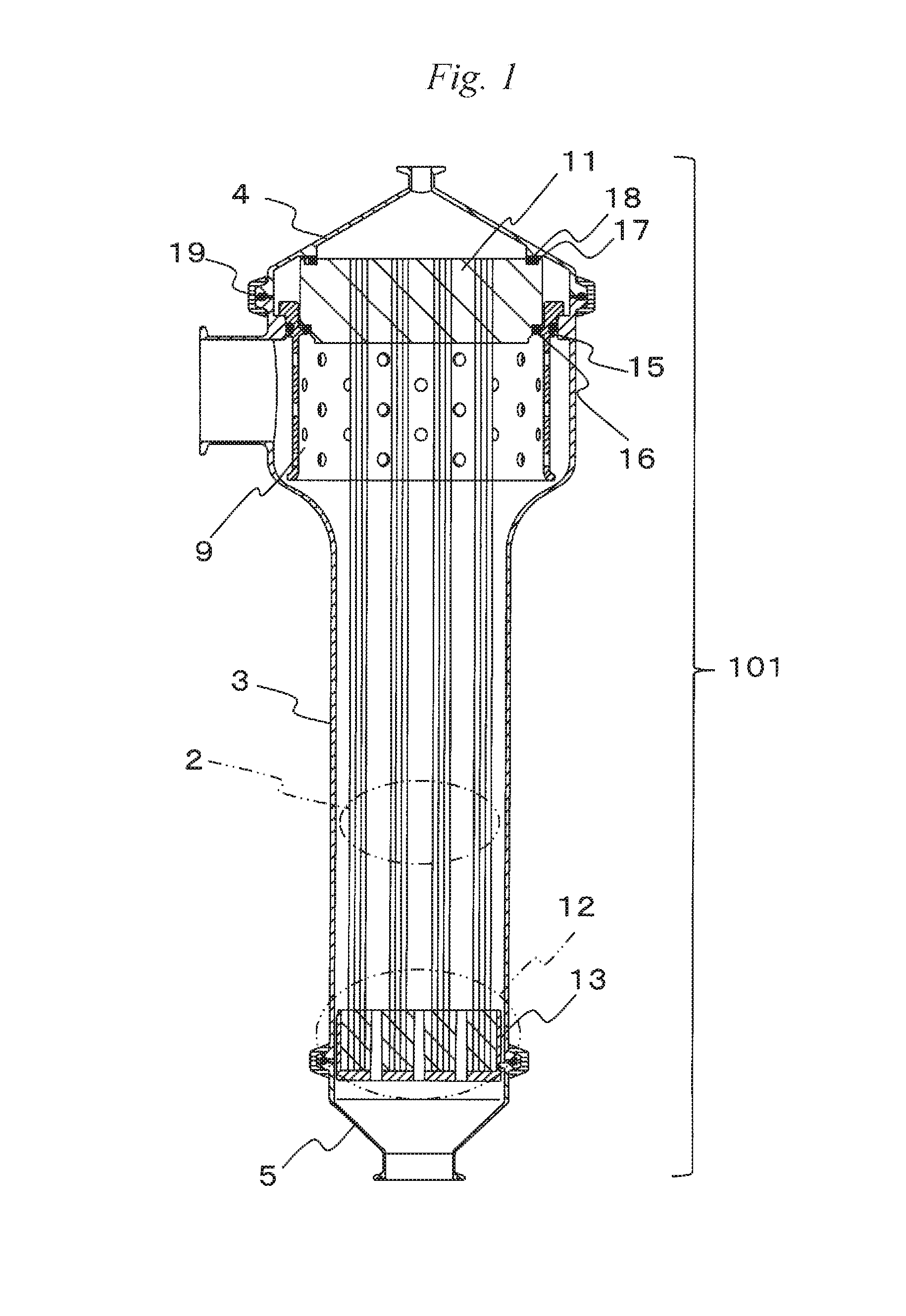
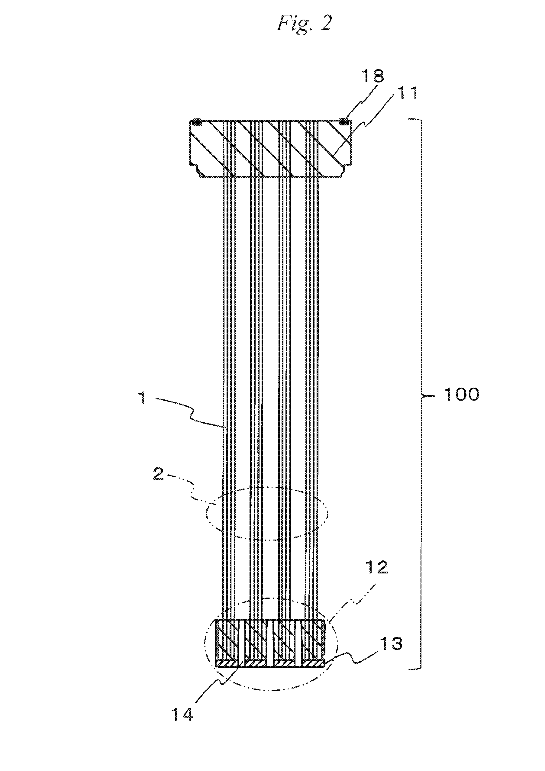
[0081]The configuration of a hollow-fiber membrane module of a first embodiment of the present invention is explained while referring to drawings. FIG. 1 is a diagrammatic vertical sectional view of a cartridge type hollow-fiber membrane module of the embodiment of the present invention. A cartridge type is described here as an example where a housing is separable from hollow-fiber membrane bundles; however, embodiments of the present invention are not limited to this case but may be any others where the first bundling and fixing part and the flow regulation cylinder, as well as the housing and the flow regulation cylinder may be liquid-tightly fixed by bonding.

[0082]In the case where the flow regulation cylinder is not fixed by bonding, the flow regulation cylinder may be easily reused and, in addition, it does not have an adhesive face and is held by a seal, and therefore has another advantage of no risk of peeling at an adhesive face.

[0083]The cartridge type hollow-fiber membrane...

second embodiment

[0144]The configuration of a cartridge type hollow-fiber membrane module 101B according to a second embodiment of the present invention is explained with reference to FIG. 28 and FIG. 29.

[0145]FIG. 28 is a diagrammatic vertical sectional view around the first bundling and fixing part 11 of the cartridge type hollow-fiber membrane module 101B of the second embodiment. Differing from that in the first embodiment, the inner periphery of the flow regulation cylinder (cylindrical case) 9B and the outer periphery of the first bundling and fixing part 11 are fixed by bonding in this configuration. Also differing from that of the first embodiment, this module can be used in a usage environment in a range not causing any excessive peeling to provide leakage on the raw liquid side and the filtrated liquid side, such as hot water sterilization or gas sterilization. Unless otherwise specifically referred to hereinunder, the same configuration as that of the cartridge type hollow-fiber membrane ...

third embodiment

[0147]The configuration of a cartridge type hollow-fiber membrane module 101C according to a third embodiment of the present invention is explained with reference to FIG. 30 and FIG. 31.

[0148]FIG. 30 is a diagrammatic vertical sectional view around the first bundling and fixing part 11C of the cartridge type hollow-fiber membrane module 101C of the third embodiment. Differing from that in the first embodiment, this configuration does not have the flow regulation cylinder 9. Unless otherwise specifically referred to hereinunder, the same configuration as that of the cartridge type hollow-fiber membrane module 101 of the first embodiment is applicable to the configuration of the cartridge type hollow-fiber membrane module 101C. The members having the same function as that of the members described in the first embodiment are given the same signs herein, and describing them is omitted.

[0149]The cartridge type hollow-fiber membrane module 101C of the third embodiment has nearly the same ...


PUM


Abstract

A housing (30) of a hollow-fiber membrane module (101) is so configured as to have a small-diameter part (3B) having an inner diameter smaller than an inner diameter of a flow regulation cylinder (9) facing a part of the housing (30) on which a nozzle (8) is provided, and which is arranged on a lower side than a lower end of the flow regulation cylinder (9) in an axial direction of the hollow-fiber membrane module (101); or the flow regulation cylinder (9) is so configured as to have a small-diameter part (9G) which has an inner diameter smaller than the inner diameter of the flow regulation cylinder (9) facing the part of the housing (30) on which the nozzle (8) is provided, and which is arranged on a lower side than the existing region of the flow regulation holes (10) in the axial direction of the hollow-fiber membrane module (101).

Description

CROSS-REFERENCE TO RELATED APPLICATIONS[0001]This is the U.S. National Phase application of PCT International Application No. PCT / JP2014 / 078407, filed Oct. 24, 2014, and claims priority to Japanese Patent Application No. 2013-271328, filed Dec. 27, 2013 and Japanese Patent Application No. 2014-071767, filed Mar. 31, 2014, the disclosures of each of these applications being incorporated herein by reference in their entireties for all purposes.FIELD OF THE INVENTION[0002]The present invention relates to a hollow-fiber membrane module for use in the fields of water treatment, fermentation industry, production of medicines, food industry, etc.BACKGROUND OF THE INVENTION[0003]Fermentation methods which are methods for substance production involving incubation of microorganisms or cells to be incubated can be roughly classified into a batch fermentation method where microorganisms or cells to be incubated as well as a starting material are prepared in every fermentation step, and a contin...

Claims


Application Information

Patent Timeline
IPC IPC(8): B01D63/02
CPCB01D63/02B01D2313/04B01D2313/08B01D2315/10B01D2313/20B01D2313/44B01D2313/13B01D63/024B01D65/003B01D2313/23B01D2315/08B01D2313/201B01D2313/205B01D69/08B01D2313/02B01D2313/042B01D2313/041
Inventor MATSUMOTO, HIROSHIIKEDA, MIKIKOKOBAYASHI, ATSUSHISHIMURA, SHUNTAKEUCHI, NORIHIROKANAI, HIROAKI
Owner TORAY IND INC
Learn More