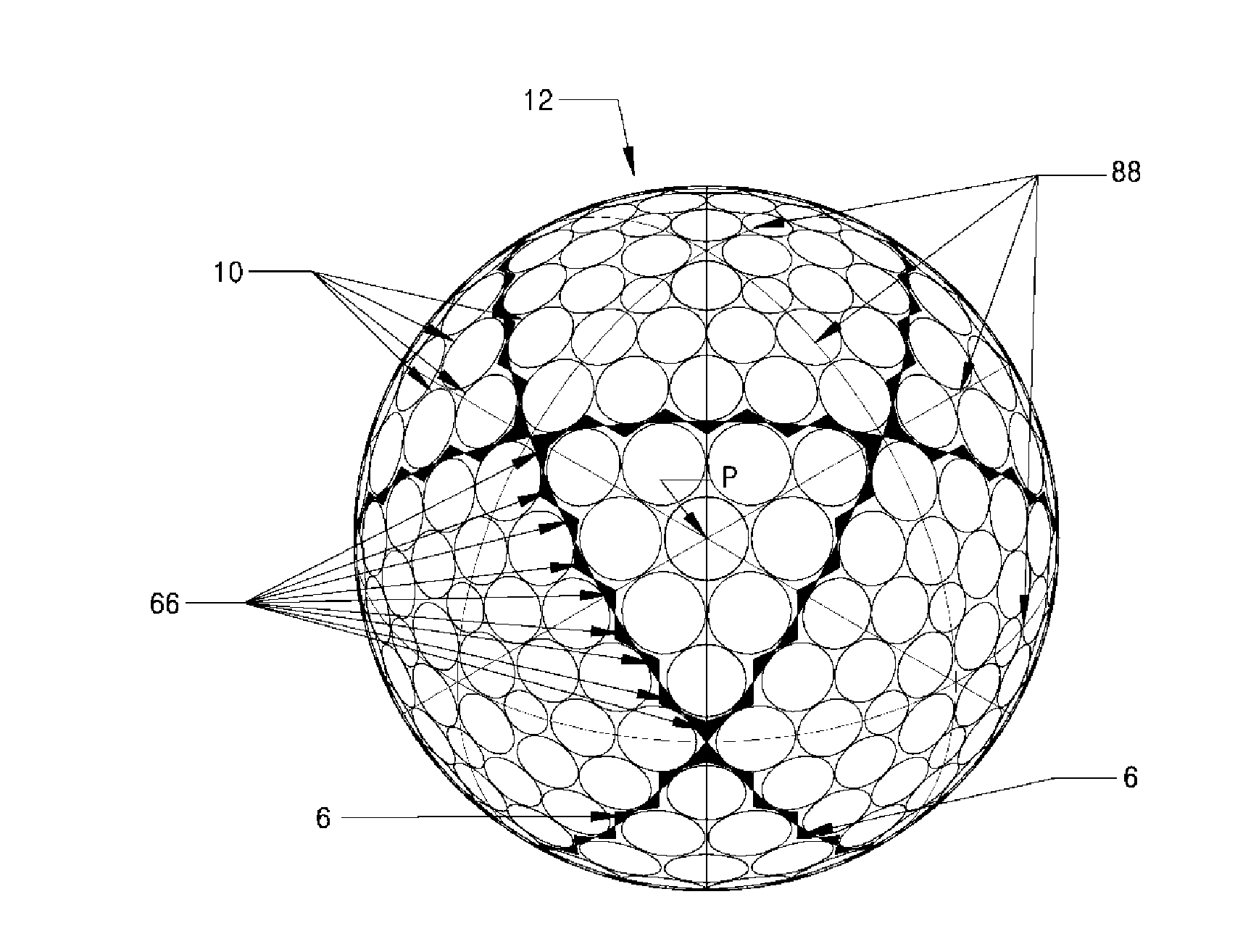
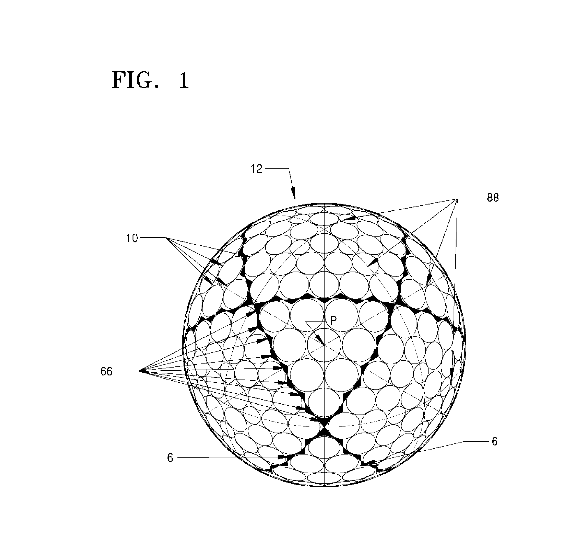
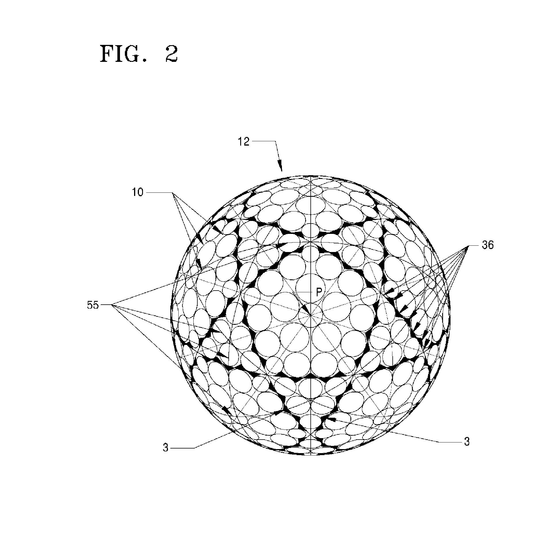
Golf ball having surface divided by triangular concave sectors
a golf ball and concave sector technology, applied in the field of golf balls, can solve the problems of reducing affecting the directional consistency of the ball, and affecting the directional consistency, so as to improve the dimple area ratio, prevent damage to the dimple, and facilitate the buffing process
- Summary
- Abstract
- Description
- Claims
- Application Information
AI Technical Summary
Benefits of technology
Problems solved by technology
Method used
Image

Examples
Embodiment Construction
[0047]Reference will now be made in detail to exemplary embodiments, examples of which are illustrated in the accompanying drawings, wherein like reference numerals refer to like elements throughout. In this regard, the present exemplary embodiments may have different forms and should not be construed as being limited to the descriptions set forth herein. Accordingly, the exemplary embodiments are merely described below, by referring to the figures, to explain aspects of the present description.
[0048]In general, dimples are formed in a surface of a golf ball because the role of dimples is important in terms of aerodynamics. As a golf ball flies to a target position with a backspin, the dimples make the air flow slowly under the golf ball which increasing pressure and the air flow fast above the golf ball which decreasing pressure, thereby generating the lift by Bernoulli's principle that enables longer flight. In this state, pressure drag and friction drag increase as well. It is we...
PUM
 Abstract
Description
Claims
Application Information
 - R&D
- Intellectual Property
- Life Sciences
- Materials
- Tech Scout
- Unparalleled Data Quality
- Higher Quality Content
- 60% Fewer Hallucinations
Browse by: Latest US Patents, China's latest patents, Technical Efficacy Thesaurus, Application Domain, Technology Topic, Popular Technical Reports.
© 2025 PatSnap. All rights reserved.Legal|Privacy policy|Modern Slavery Act Transparency Statement|Sitemap|About US| Contact US: help@patsnap.com