
Mechanical Dose Expelled Indicator

a dose expulsion indicator and mechanical technology, applied in the direction of intravenous devices, automatic syringes, syringes, etc., can solve the problems of mislead post dose readings, inattention users may be left in doubt after the administration as to the size of the dose actually received, etc., to eliminate or reduce at least one drawback

Inactive Publication Date: 2016-11-03
NOVO NORDISK AS
View PDF1 Cites 8 Cited by
  • Summary
  • Abstract
  • Description
  • Claims
  • Application Information

AI Technical Summary

Benefits of technology

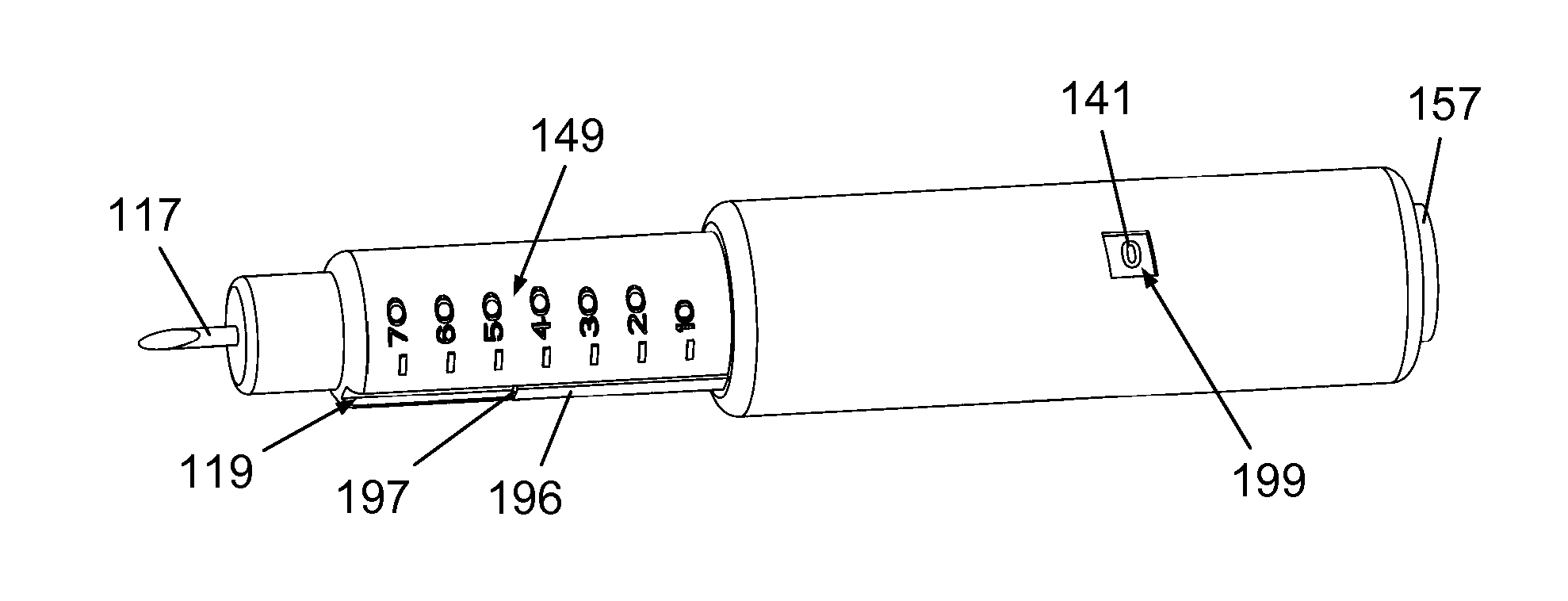
The invention aims to solve issues in prior art devices by providing a device that consistently shows the amount of medication delivered, and allows for easy inspection of the dosage progress during use. This device uses a direct indication from the end of the injection needle, which allows for real-time confirmation of dose delivery. This ensures that the intended dose is being delivered properly and can alert the user if there are any issues with the fluid pathway. The visibility of the dose indicator is directly correlated to the distance travelled by the piston rod, so the user can estimate the amount of medication remaining in the reservoir.

Problems solved by technology

In everyday life a busy schedule may give rise to negligence towards the various preparations leading up to a drug administration, in particular for people who are seasoned in self-administration.
If the device used for administration of the drug does not offer an automatic storing of the ejected dose an inattentive user may be left in doubt after the administration as to the size of the dose actually received.
An inattentive user may position the scale such that the zero value is somewhat offset from the front edge of the piston, inevitably resulting in a misleading post dose reading.
Furthermore, since the dose related numbers are arranged on the piston rod and the piston rod only moves in one direction for the emptying of the cartridge it appears impossible with this construction to reset the numbers providing the dose related indication such that every post dose indication directly reflects the dose delivered.

Method used


Image

  • Mechanical Dose Expelled Indicator
  • Mechanical Dose Expelled Indicator
  • Mechanical Dose Expelled Indicator

Examples


Embodiment Construction

[0050]When in the following relative expressions, such as e.g. “upwards” and “downwards” and “clockwise” and “counter-clockwise”, are used these refer to the appended figures and not necessarily to an actual situation of use. The shown figures are schematic representations for which reason the configuration of the different structures as well as their relative dimensions are intended to serve illustrative purposes only.

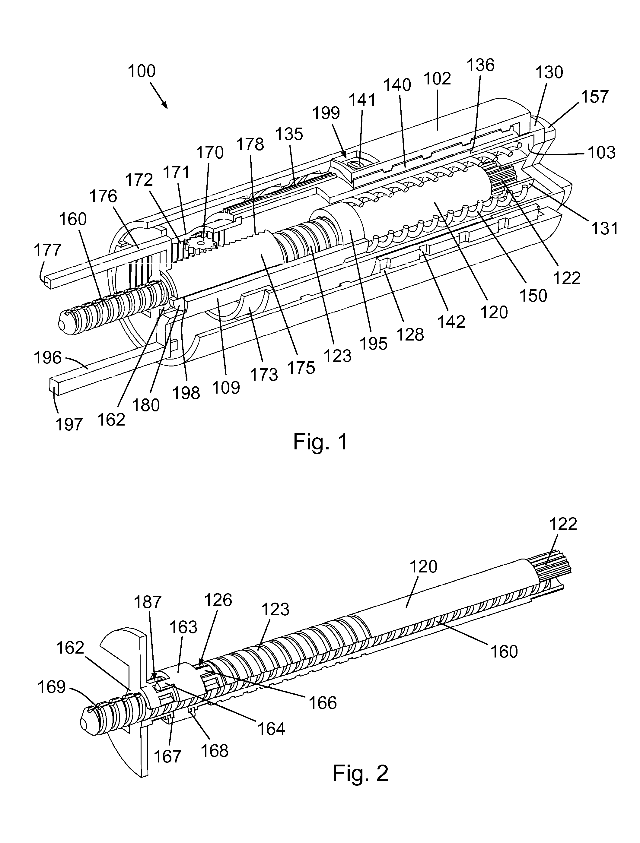
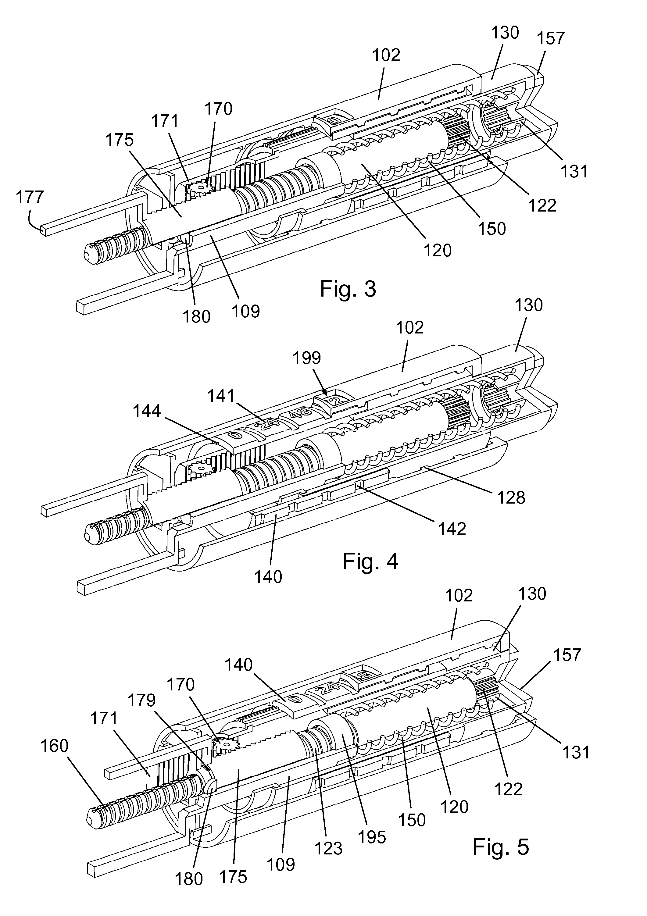
[0051]FIG. 1 is a perspective view of a portion of an injection device 100 according to an embodiment of the invention, specifically of a proximal portion of the injection device 100, carrying a dose engine. The injection device 100 is in a pre-use state and portions of some elements thereof have been removed from the figure to provide a detailed overview of the construction.

[0052]The injection device 100 is of the so-called pen injector type and has a tubular housing 102 extending along a longitudinal general axis and accommodating a number of functional components. ...


PUM


Abstract

The present invention concerns a dosing unit for an injection device (100) and an injection device incorporating the dosing unit. The dosing unit comprises a housing (102) extending along a longitudinal axis from a proximal housing end to a distal housing end, the distal housing end being adapted for connection with a variable volume reservoir, an injection mechanism for expelling a dose of a substance held in a connected variable volume reservoir, the injection mechanism being arranged at least partially in the housing (102) and comprising an injection button (157), a dose defining structure (140) configured to move from a start position to an end-of-dose position in response to a dose expelling operation of the injection button (157), and a piston rod (160) configured to move in a dose delivery direction from a first position to a second position in response to a movement of the dose defining structure (140) from the start position to the end-of-dose position, and a dose delivered indicator (109) configured to move axially in a distal direction from a dose ready position to a dose delivered position in response to the movement of the dose defining structure (140) from the start position to the end-of-dose position, wherein during movement from the dose ready position to the dose de livered position a portion of the dose delivered indicator (109) emerges increasingly from the distal housing end.

Description

FIELD OF THE INVENTION[0001]The present invention relates to dose delivery devices for administration of medicinal substances.BACKGROUND OF THE INVENTION[0002]Most modern devices for multiple dose delivery of pharmaceutical substances comprise a dose setting mechanism that allows a user to selectively set a dose to be dispensed from a substance containing reservoir. Some treatment regimens require setting and administration of a dose of drug that varies over time, whereas other treatment regimens require repeated setting and administration of a fixed dose of drug. In some cases the fixed dose may need to be adjusted over time, for example during a dosage titration period.[0003]A common type of drug delivery device is the so-called pen injector which is a pen-shaped injection device used for intermittent subcutaneous administration of an active agent. Typically, such a pen injector allows the user to turn a dial about a general longitudinal axis to set a desired dose. If by accident ...

Claims


Application Information

Patent Timeline
IPC IPC(8): A61M5/315A61M5/24A61M5/20A61M5/28
CPCA61M5/31553A61M5/31585A61M5/282A61M2005/2403A61M5/31566A61M5/20A61M2005/3126A61M5/2425A61M5/31583A61M5/3202A61M2005/2073
Inventor ANDERSEN, MADS GROENLUND
Owner NOVO NORDISK AS
Learn More