Eureka AIR delivers breakthrough ideas for toughest innovation challenges, trusted by R&D personnel around the world.

Evacuation plan design

a technology of evacuation plan and evacuation plan, applied in the direction of instruments, surveying and navigation, signalling system details, etc., can solve the problems of enumerating each possible path, and enumerating the typical change of the road network

Inactive Publication Date: 2016-10-27
NAT ICT AUSTRALIA
View PDF0 Cites 14 Cited by
  • Summary
  • Abstract
  • Description
  • Claims
  • Application Information

AI Technical Summary

Benefits of technology

The patent describes a method for designing evacuation plans for large-scale flood scenarios using a network configuration approach. The approach has two main advantages: critical groups are determined and paths are added for the critical groups to determine an updated solution. The paths are added on-demand, so no possible paths need to be considered. This reduces the computational complexity of the problem. The paths are the same for all members of a group, so entire zones can be evacuated in the same fashion. The method also reduces the number of variables by using the same flow variable for each path, rather than the number of edges. The updated network configuration decisions are determined simultaneously with the determination of the updated departure schedule and the updated paths, improving the efficiency of the evacuation process.

Problems solved by technology

Natural and man-made disasters, such as hurricanes, floods, and bushfires, affect numerous populated areas and may endanger the lives and welfare of entire populations.
The road network is typically changing by the influence of the disaster and the evacuation itself, with for instance flooded roads or accidents.
Any method that scales linearly with the number of possible paths; such as enumerating each possible path, quickly becomes infeasible as a result of the large number of paths.
In addition, existing methods rely on the simplifying assumption that evacuees can flow freely in the network, which is not applicable in practice.
It is therefore difficult to design an evacuation plan for a substantial area using existing methods.

Method used


Image

  • Evacuation plan design
  • Evacuation plan design
  • Evacuation plan design

Examples


Embodiment Construction

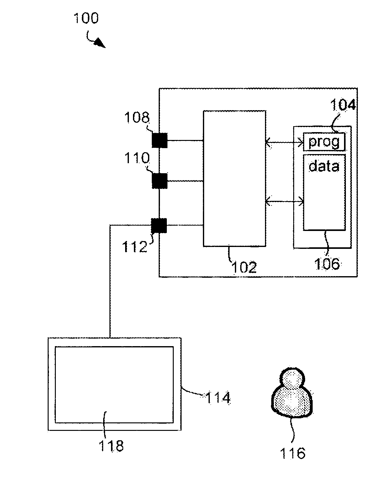
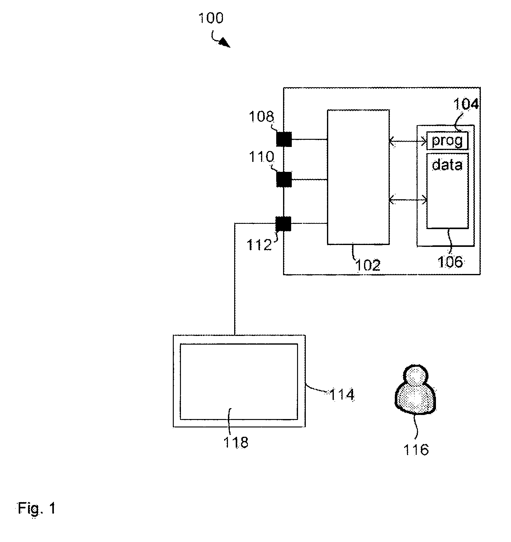
[0058]FIG. 1 illustrates a computer system 100 for planning movement of multiple groups over a transport network. The computer system 100 includes a processor 102 connected to a program memory 104, a data memory 106, first data port 108 and second data port 110. The first data port 108 and the second data port 110 may be the same data port. The processor is also connected to a user port 112 that interfaces the processor 102 with a display 114 operated by a central decision maker 116. In one example, the program memory 104 is a non-transitory computer readable medium, such as a hard drive, a solid-state disk or CD-ROM.

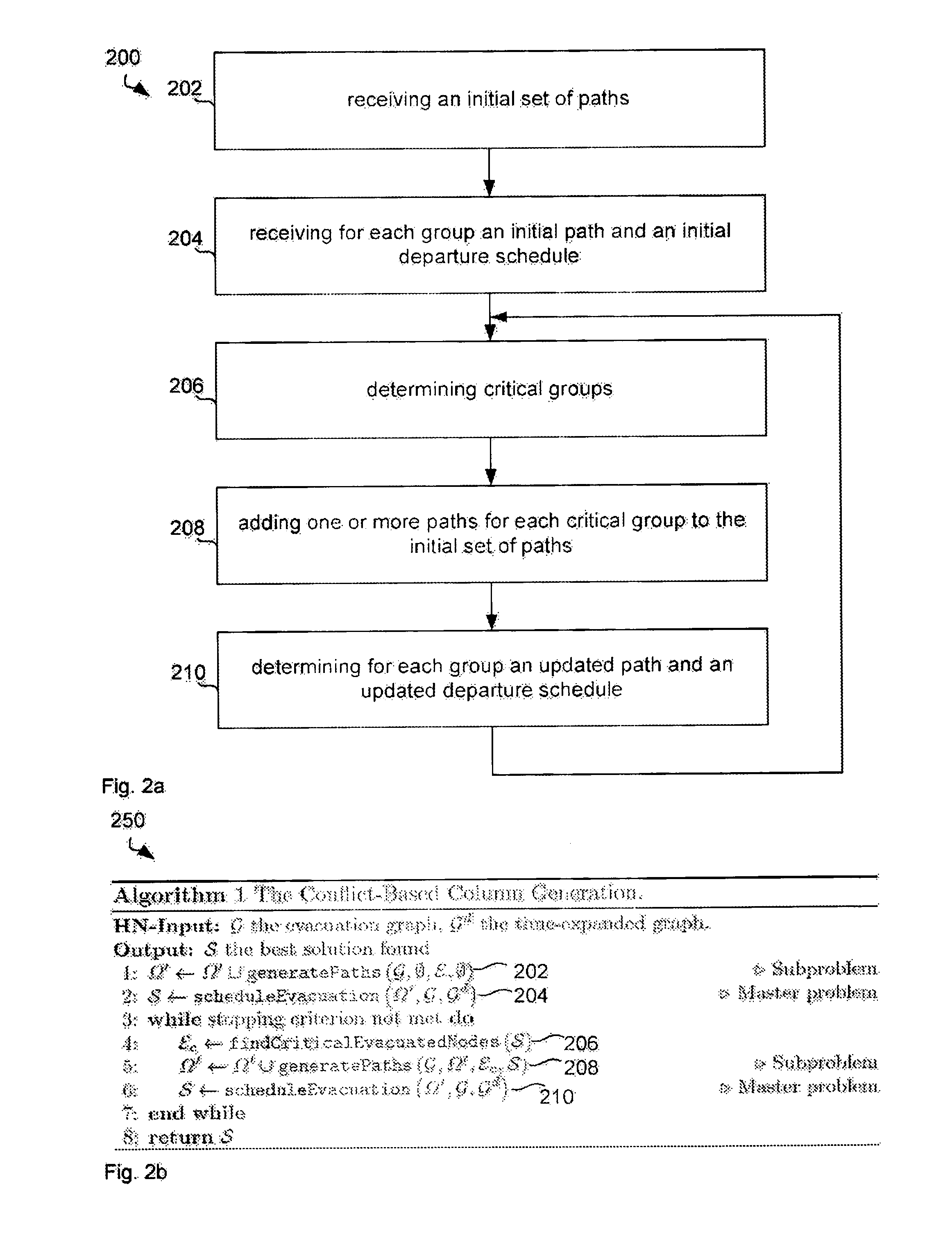
[0059]Software, that is an executable program comprising computer executable instructions, stored on program memory 104 causes the processor 102 to perform the method in FIG. 2, that is, the processor determines critical groups, adds one or more paths for each critical group to an initial set of paths, and determines for each group a departure schedule and a path to the...


PUM


Abstract

This disclosure relates to planning movement of multiple groups over a transport network, for example, but not limited to, the evacuation of persons from geographical zones. A processor receives an initial set of paths for the multiple groups to move through the transport network to respective arrival locations and for each group an initial path to the respective arrival location and an initial departure schedule. The processor then determines based on the initial departure schedules and initial paths one or more critical groups that violate a movement performance threshold and further determines based on the transport network an updated set of paths by adding one or more paths for each critical group to the initial set of paths. Finally, the processor determines for each group an updated path to the arrival location and an updated departure schedule based on the updated set of paths.

Description

CROSS-REFERENCE TO RELATED APPLICATIONS[0001]The present application claims priority from Australian Provisional Patent Application No 2013902454 Filed on 2 Jul. 2013, the content of which is incorporated herein by reference.TECHNICAL FIELD[0002]This disclosure relates to planning movement of multiple groups over a transport network, for example, but not limited to, the evacuation of persons from geographical zones.BACKGROUND[0003]Natural and man-made disasters, such as hurricanes, floods, and bushfires, affect numerous populated areas and may endanger the lives and welfare of entire populations. Evacuation orders are some of the most important decisions performed by emergency services: they ensure the safety of people at risk by instructing them to evacuate the threatened region, be it a building (e.g., fire), a neighbourhood (e.g., industrial hazard), or a whole region (e.g., flood). Evacuation planning also arises at strategic, tactical, and operational levels. At a strategic lev...

Claims


Application Information

Patent Timeline
Patent Type & Authority Applications(United States)
IPC IPC(8): G06Q90/00G01C21/34
CPCG01C21/3407G06Q90/205G01C21/3446G08B7/066
Inventor PILLAC, VICTORVAN HENTENRYCK, PASCALEVEN, CAROLINE
Owner NAT ICT AUSTRALIA
Why Eureka
Eureka Blog
Learn More