
A blast attenuator

a technology of attenuator and blast, which is applied in the direction of blasting, armoured vehicles, vehicles, etc., can solve the problems of only providing attenuation to attenuators, occupants may be injured, and damage to both vehicles and their occupants, so as to achieve the effect of attenuating the energy of a blas

Active Publication Date: 2016-10-27
ARMORWORKS HLDG
View PDF0 Cites 7 Cited by
  • Summary
  • Abstract
  • Description
  • Claims
  • Application Information

AI Technical Summary

Benefits of technology

The invention is a blast attenuator that uses a container with a stirring element to reduce the energy of a blast. The container has stationary elements that create a boundary layer condition at the outer wall, minimizing friction between the particulate media and the container. The stirring element is designed to prevent movement of the particulate media while creating a boundary layer and maximizing friction capacity. The blast attenuator may have two support mechanisms that provide more efficient resistance to static tilting tendencies while the passenger is seated. The rack moves upwards prior to the slam-down stroke, allowing the pinion to rotate without any resistance from the particulate media.

Problems solved by technology

Such explosive devices are typically triggered automatically by mobile trigger or the weight of the vehicle passing over the device and can cause catastrophic damage to both the vehicle and its occupants.
Nevertheless, while armor can prevent injury from shrapnel, occupants may be injured by the initial impact of the blast which violently displaces the vehicle and the subsequent “slam-down” as the vehicle returns to the ground.
However, such blast attenuators normally only provide attenuation of movement in a single direction (typically in the vertical direction).
Moreover, the arresting load (or attenuating force) provided by such blast attenuators is not constant and varies depending on the applied blast load magnitude and the speed and acceleration of compression.

Method used


Image

  • A blast attenuator
  • A blast attenuator
  • A blast attenuator

Examples


Embodiment Construction

[0062]FIG. 1 shows a blast attenuator 2 according to an embodiment of the invention.

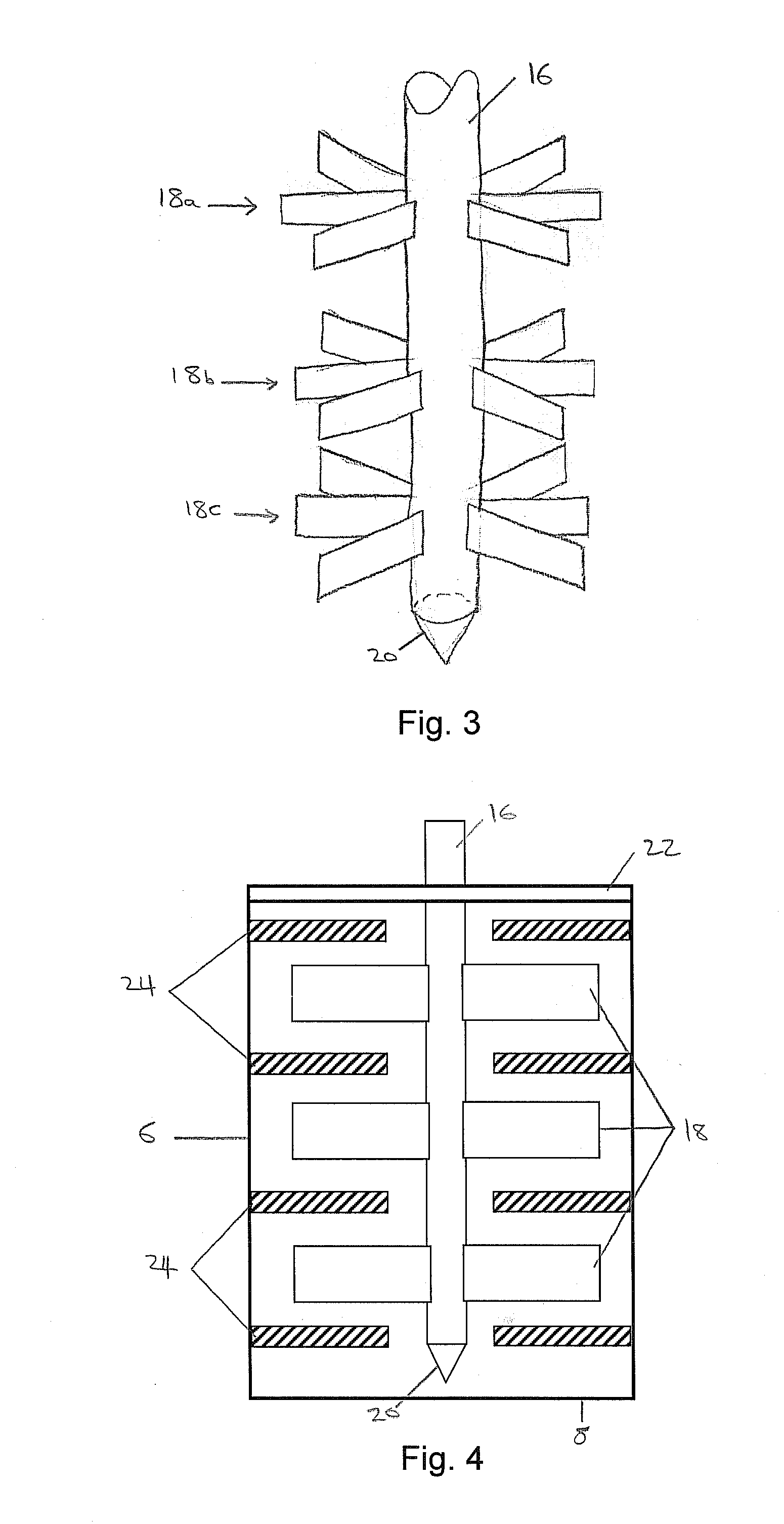
[0063]The blast attenuator 2 comprises a container 4 having a cylindrical outer wall 6 and a base 8.

[0064]The container 4 defines a cavity 10 bounded by the outer wall 6 and the base 8. The cavity 10 is at least partially filled with a particulate media 12. The particulate media 12 may comprise granules, fibers and / or flakes of a suitable material, and will be described in more detail below. For clarity, only the top surface of the particulate media 12 is shown, however, it will be appreciated that the particulate media 12 fills the cavity 10 between the base 8 and the top surface shown.

[0065]The blast attenuator 2 further comprises a stirring element 14 which is received in the cavity 10 of the container 4, but is freely movable relative to the container 4. The stirring element 14 comprises a shaft 16 and a plurality of paddles 18 which extend outwardly from the shaft 16. As shown, the shaft 16 tape...


PUM


Abstract

Methods and apparatus are provided for a blast attenuator having a container with an outer wall that defines a cavity in which a particulate media is disposed, and a stirring element disposed in and moveable relative to the container. At least a portion of the stirring element extends into the particulate media, wherein, in use, the particulate media provides resistance against movement of the stirring element relative to particulate media so as to attenuate the energy of a blast.

Description

TECHNICAL FIELD AND BACKGROUND[0001]The invention relates to a blast attenuator and particularly, but not exclusively, to a blast attenuator for a seat, blast floor or V-shaped hull of a vehicle used in a combat zone.[0002]In a combat zone, vehicles such as tanks, personnel carriers including armored personnel carriers, trucks, and the like, may be targets of explosive devices, such as land mines, rocket propelled grenades and other improvised explosive devices (IEDs). Such explosive devices are typically triggered automatically by mobile trigger or the weight of the vehicle passing over the device and can cause catastrophic damage to both the vehicle and its occupants.[0003]It is desirable to protect combat vehicles and their occupants from such explosive devices. For example, vehicles may be equipped with armor plating (for example, an armor-plated V-hull) to prevent blasts from penetrating the internal space of the vehicle. Nevertheless, while armor can prevent injury from shrapn...

Claims


Application Information

Patent Timeline
Patent Type & Authority Applications(United States)
IPC IPC(8): F41H7/04
CPCF41H7/046F41H7/042F42D5/045
Inventor LEE, YUK LRICHARDS, IAN
Owner ARMORWORKS HLDG
Learn More