
Fluid connector with exhaust valve

a technology of fluid connector and fluid connector, which is applied in the field of devices, can solve the problems of deprived of the restorative sleep necessary, excessive tiredness, and high complexity, and achieve the effects of improving fluid flow, facilitating diffusion and dissipation of gas blades, and improving exhalation

Active Publication Date: 2016-10-27
KONINKLJIJKE PHILIPS NV
View PDF18 Cites 12 Cited by
  • Summary
  • Abstract
  • Description
  • Claims
  • Application Information

AI Technical Summary

Benefits of technology

The improved fluid connector apparatus with an improved exhalation insert provides an improved exhalation feature. The exhalation feature allows breathed gas to be output in the form of elongated blades of gas, which have better fluid flow compared to conventional circular jets of gas. The elongated flow channels also help to entrain atmospheric gases and facilitate the diffusion and dissipation of the gas blades, resulting in reduced acoustic signature. Overall, this design improves the performance of the fluid connector apparatus by allowing for improved gas output in large volumes with reduced velocities.

Problems solved by technology

Because their sleep is constantly disrupted, they are deprived of the restorative sleep necessary for efficient functioning of body and mind.
OSA also causes excessive tiredness.
Fluid connectors such as the aforementioned entrainment elbow are typically highly complex and require three or more directions of draw during an injection molding process and may further include other components that may be separately molded and then ultrasonically welded or otherwise attached to the elbow to form the fluid connector.
While a greater number of relatively smaller holes can result in quieter exhaust flow, it has been known that the extent to which such holes can be reduced in size is limited due to shortcomings in manufacturing reliability.

Method used


Image

  • Fluid connector with exhaust valve
  • Fluid connector with exhaust valve
  • Fluid connector with exhaust valve

Examples


first embodiment

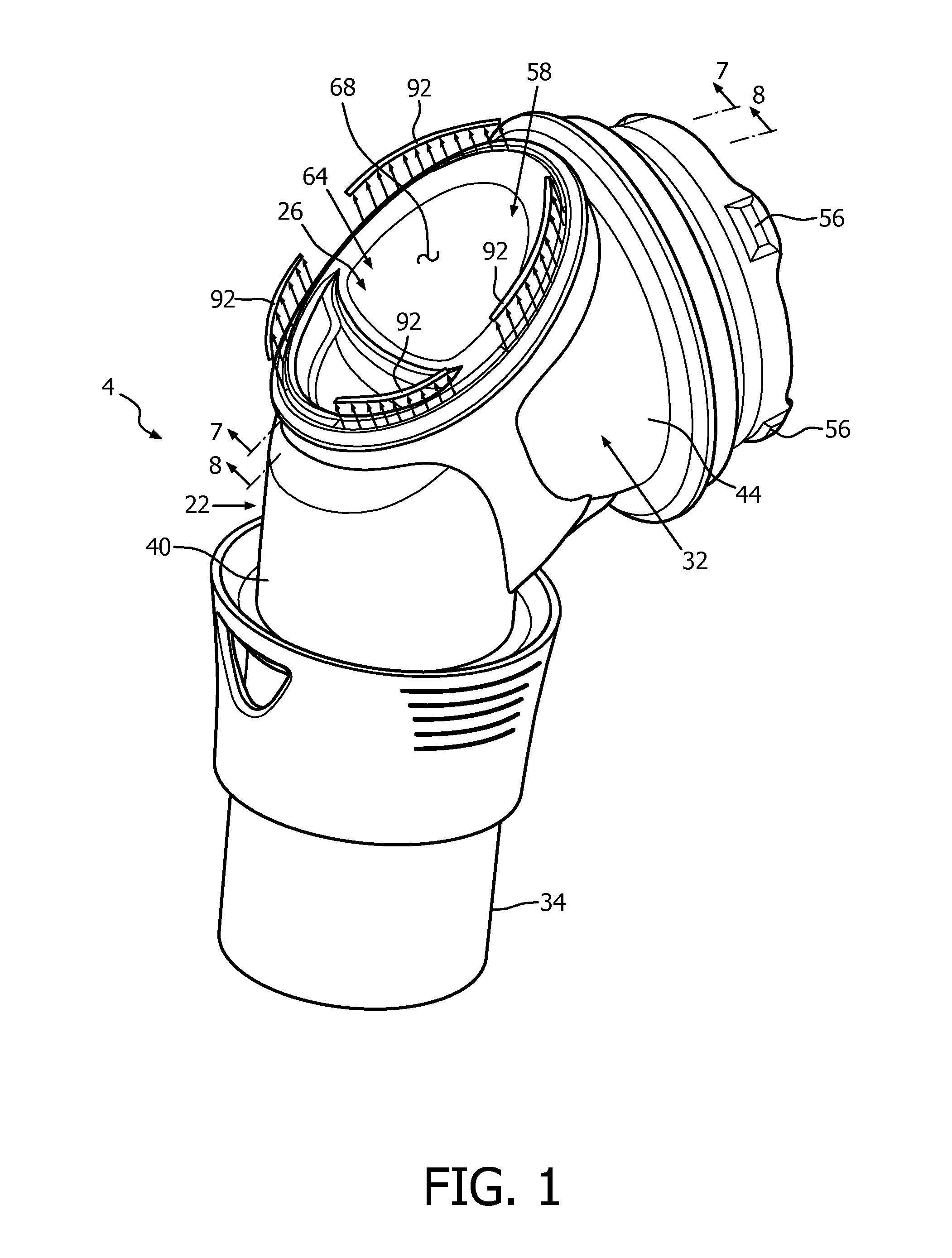
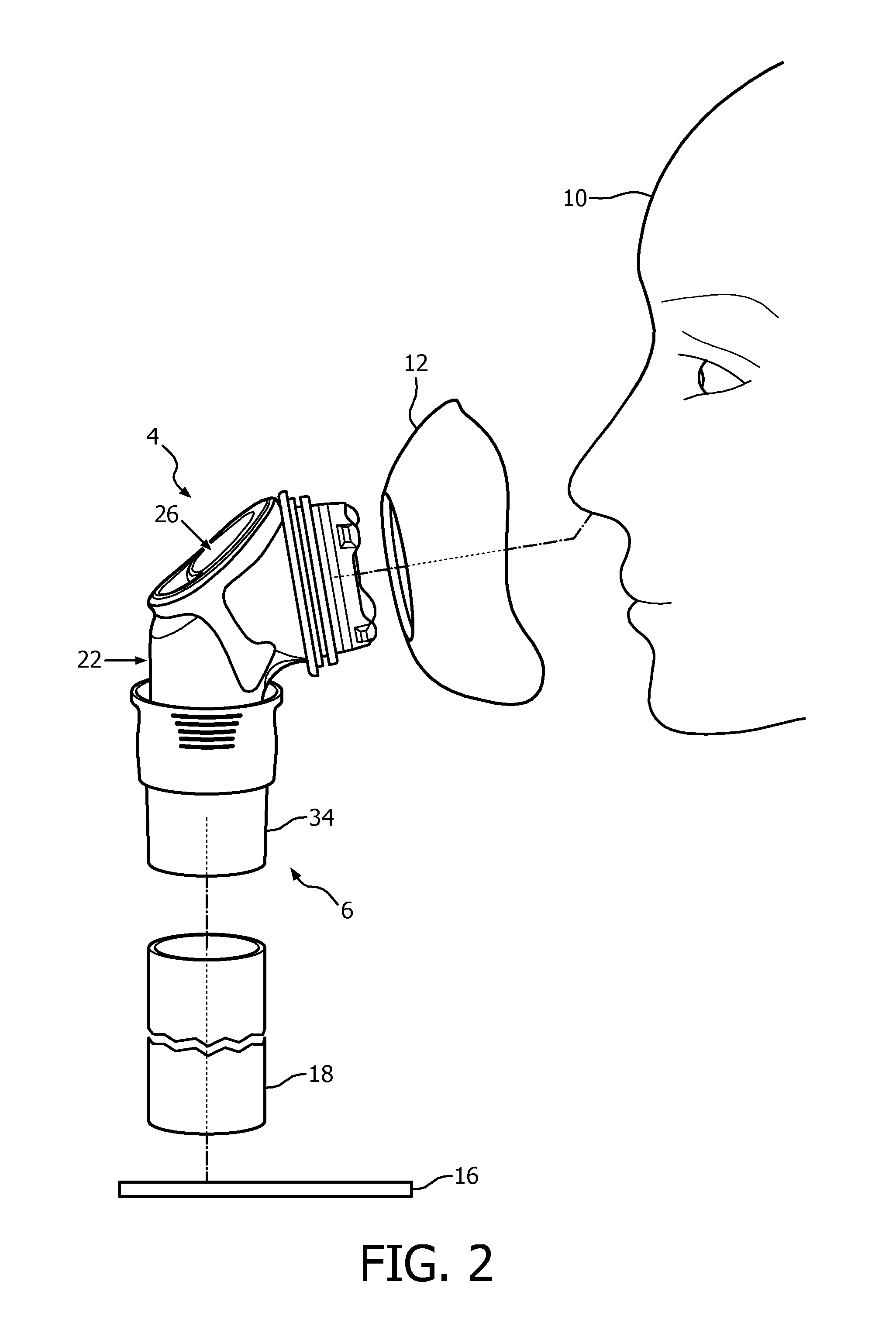
[0032]An improved fluid connector apparatus 4 in accordance with the disclosed and claimed concept is depicted generally in FIGS. 1-11. Fluid connector apparatus 4 is advantageously employable in an improved respiratory therapy apparatus 6 that is depicted in FIG. 2 as providing respiratory therapy to a patient 10. Respiratory therapy apparatus 6 of FIG. 2 can be said to include a schematically depicted interface device 12 which may be, by way of example, a nasal or nasal / oral mask or other such device that is suited to patient 10. Fluid connector apparatus 4 places interface device 12 in fluid communication with a source of breathing gas 16 such as a CPAP machine or other such source of breathing gas. A supply hose 18 typically extends between source of breathing gas 16 and fluid connector apparatus 4.

[0033]As can be understood from FIGS. 3 and 4, fluid connector apparatus 4 can be said to include a fluid connector 22 and an improved exhalation insert 26 in accordance with an aspec...

second embodiment

[0049]An improved exhalation insert 426 in accordance with the disclosed and claimed concept is depicted generally in FIGS. 12 and 13. Exhalation insert 426 can be employed in place of exhalation insert 26 on fluid connector 22 to provide another improved connector apparatus in accordance with the disclosed and claimed concept. Exhalation insert 426 is similar to exhalation insert 26 except that it does not include mounting apparatus 62 or the resultant flow channels 90.

[0050]As can be seen in FIGS. 12 and 13, exhalation insert 426 includes a support 458 having a central structure 464 that has an interior surface 466 and an exterior surface 468. Central structure 464 includes a plurality of plate elements 472 that are positioned side-by-side in a terraced fashion to cause the various plate elements 472 to each be slightly offset from one another in a direction parallel with a thickness 469 of central structure 464.

[0051]Plate elements 472 are advantageously arranged to each have the...


PUM


Abstract

An fluid connector apparatus having an exhalation insert that provides an improved exhalation feature whereby ex -haled breathing gas flows out of the fluid connector apparatus in the form of elongated blades of gas. The elongated blades of gas enable improved fluid flow when compared with conventional circular jets of gas and advantageously also entrain atmospheric gases adjacent the gas blades to facilitate diffusion and dissipation of the gas blades. The fluid connector apparatus includes one or more elongated flow channels formed between the exhalation insert and the fluid connector. The exhaust gas flows through the flow channels, and the flow channels cause the discharged gas to be output in the form of the elongated blades of gas. The exhalation feature enables the outputting of exhaled breathing gas in greater volumes, at reduced velocities, and with reduced acoustic signature.

Description

CROSS-REFERENCE TO RELATED APPLICATIONS[0001]This patent application claims the priority benefit under 35 U.S.C. §119(e) of U.S. Provisional Application No. 61 / 917,611 filed on Dec. 18, 2013, the contents of which are herein incorporated by reference.BACKGROUND OF THE INVENTION[0002]1. Field of the Invention[0003]The disclosed and claimed concept relates generally to devices that provide respiratory therapy to a patient and, more particularly, to an exhalation valve of a fluid connector that connects together a source of breathing gas and a patient interface in order to provide respiratory therapy to a patient.[0004]2. Description of the Related Art[0005]Obstructive sleep apnea (OSA) is a condition that affects millions of people from around the world. OSA is characterized by disturbances or cessation in breathing during sleep. OSA episodes result from partial or complete blockage of airflow during sleep that lasts at least 10 seconds and often as long as 1 to 2 minutes. In a given ...

Claims


Application Information

Patent Timeline
IPC IPC(8): A61M16/08A61M16/06A61M16/00A61M16/20
CPCA61M16/0816A61M16/208A61M2205/42A61M16/0057A61M16/06A61M2206/11G06F3/04166G06F3/04182G06F3/0443H03K17/9622H03K2017/9606H03K2017/9613H03K2217/94094H03K2217/960725H03K2217/96073H03K2217/96074H03K2217/960775G06F3/044
Inventor ROTHERMEL, JUSTIN EDWARD
Owner KONINKLJIJKE PHILIPS NV
Learn More