Low-nox combustion method

a combustion method and low-nox technology, applied in the field of combustion in furnaces, can solve the problems of fuel penalty, high nox emissions, and reduce the amount of heat recovered from the furnace flue gas

Active Publication Date: 2016-10-20
PRAXAIR TECH INC
View PDF1 Cites 16 Cited by
  • Summary
  • Abstract
  • Description
  • Claims
  • Application Information

AI Technical Summary

Problems solved by technology

In regenerative glass melting furnaces firing natural gas with high temperature preheated combustion air, the flame temperature becomes very high, which causes high NOx emissions.
Such a method, however, reduces the amount of heat recovered from the furnace flue gas.
If there is no additional heat recovery device downstream of the regenerator flue duct, the higher temperature flue gas then exhausts into the stack and imposes a fuel penalty and thus higher operating costs.

Method used


Image

  • Low-nox combustion method
  • Low-nox combustion method
  • Low-nox combustion method

Examples


example 1

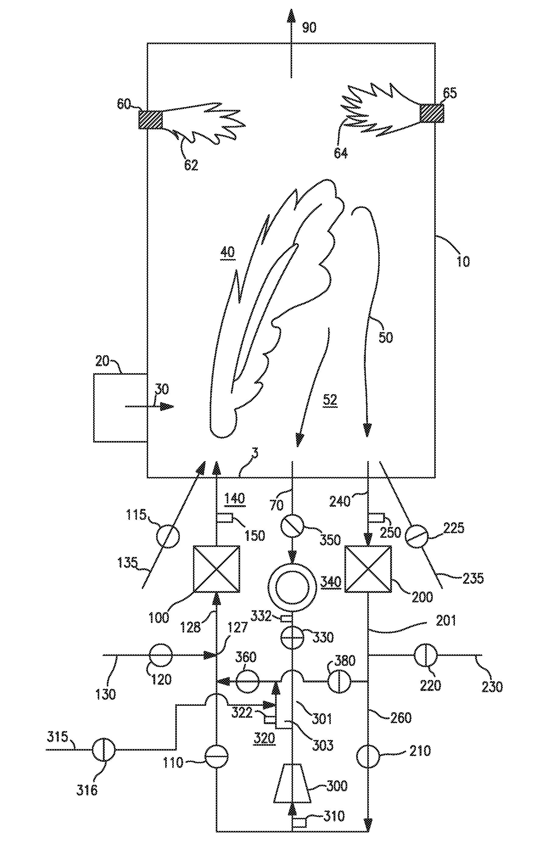
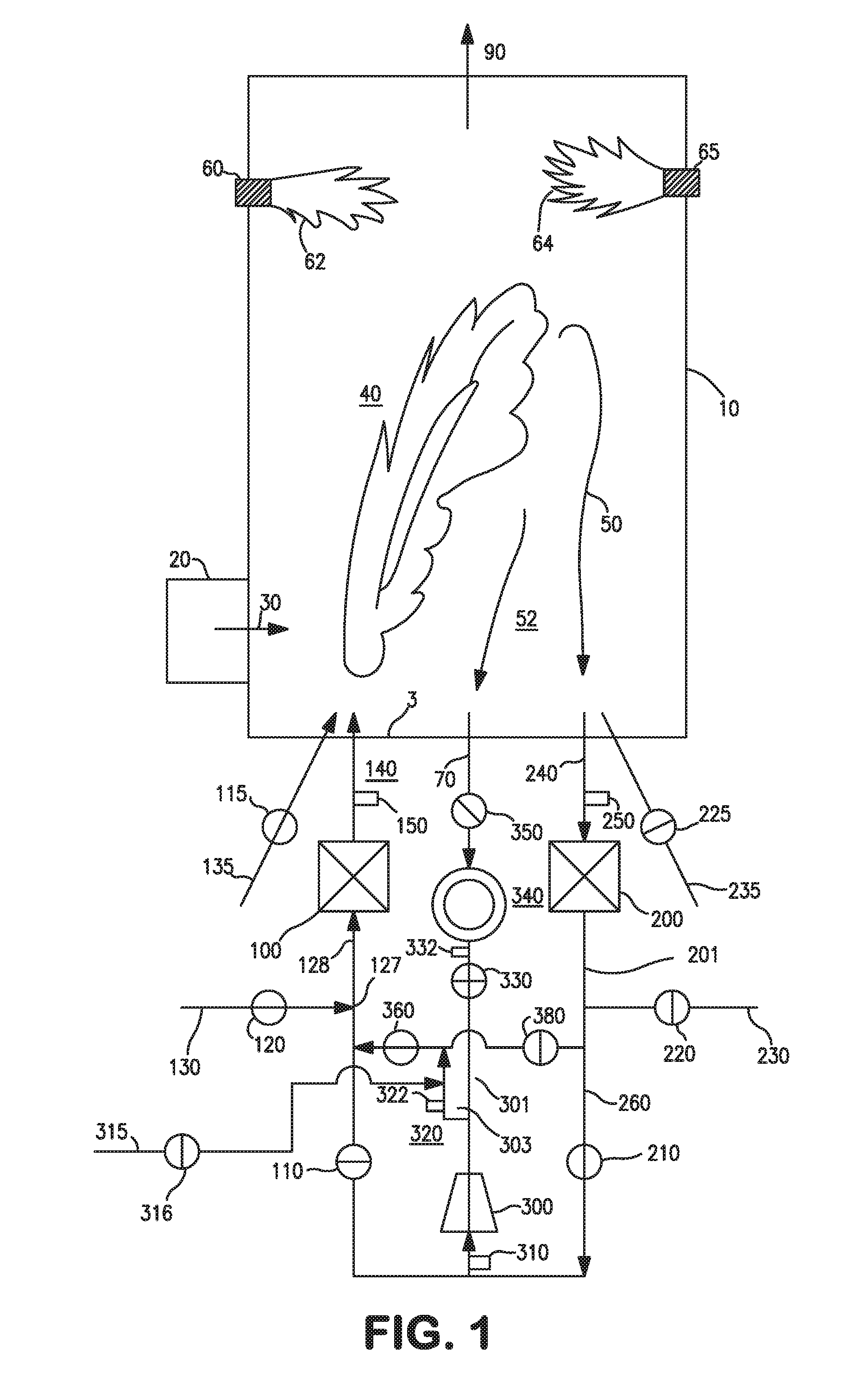
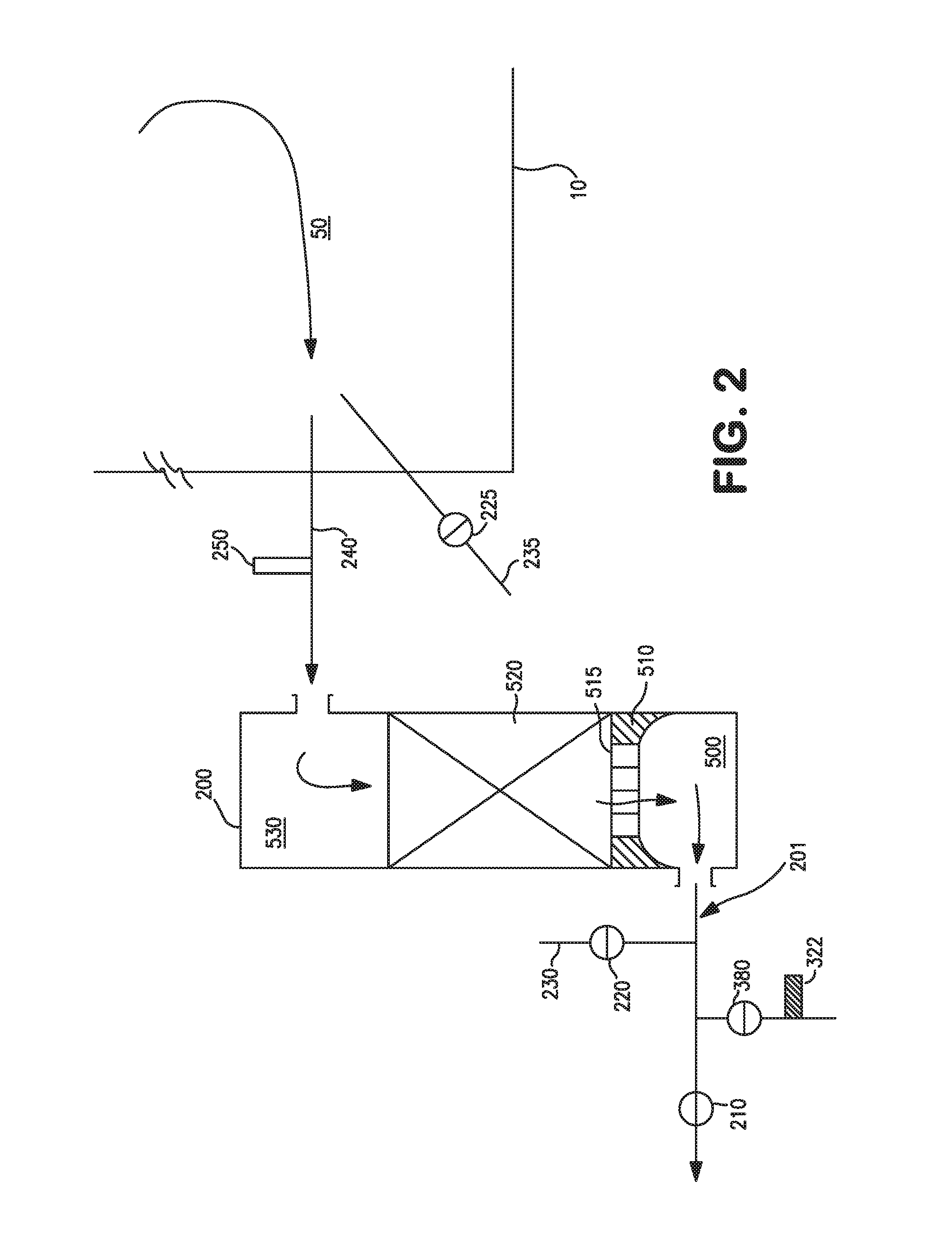
[0040]A NOx reduction apparatus and method of the present invention as shown in FIG. 1 is used for this illustration. The projected NOx reduction is summarized in Table 1 below.

[0041]Referring also to FIG. 3 and Case 1 of Table 1, one mole of flue gas is recycled through conduit (320) and mixes at location (127) of conduit (128) with one mole of reforming fuel CH4 which is fed in conduit (130) through valve (120). The RFG / NG mole ratio therefore equals one. Assuming complete reforming in checker pack (420) of regenerator (100), four moles of syngas is generated described as CH4+⅓(CO2+2H2O)→4 / 3CO+8 / 3H2 (Eq. d). After stoichiometric combustion in flame (40) of the CO and H2 gases which are thus formed with pure O2 supplied from conduit (135), the flue gas mole volume remains at four. Additional gases such as CO2 and H2O from batch / cullet and air infiltration into glass furnace (10) was estimated to be 0.51 moles and 0.45 moles, respectively.

[0042]With reference to Case 1 and FIG. 1, t...


PUM

PropertyMeasurementUnit
vol. %aaaaaaaaaa
vol. %aaaaaaaaaa
heataaaaaaaaaa

Abstract

Disclosed is a combustion method in which heated flue gas heats a regenerator through which a mixture of fuel and flue gas containing NOx is passed to undergo endothermic reactions that produce syngas and destroy NOx.

Description

CROSS REFERENCE TO RELATED APPLICATIONS[0001]This application claims the benefit of priority to U.S. provisional application Ser. No. 62 / 147,786 filed on Apr. 15, 2015, the disclosure of which is incorporated by reference herein in its entirety.FIELD OF THE INVENTION[0002]The present invention relates to combustion in furnaces such as glassmelting furnaces wherein material is fed into the furnace and is heated and / or melted by the heat of combustion that occurs within the furnace.BACKGROUND OF THE INVENTION[0003]Reducing NOx emissions has been a common environmental goal for many industries which use hydrocarbon fuels as a means of supplying heat and energy for various process needs. Typically a hydrocarbon fuel is combusted with an oxidant to release the fuel's chemical energy, as such single or multiple high temperature flames are also formed. Heat from the flame is transferred to process loads for a variety of purposes, such as to produce high pressure steam for electricity gener...

Claims


Application Information

Patent Timeline
Patent Type & Authority Applications(United States)
IPC IPC(8): F23J15/02F23L7/00F23J15/06
CPCF23J15/022F23L7/007F23J15/06C01B3/34C03B5/235C03B5/2353C03B5/237F23C9/06C01B2203/1241C01B2203/06C01B2203/0205C01B3/32F23L15/02F23C6/047F23C9/00F23G7/066F23C2202/20F23L2900/07007Y02E20/32Y02E20/34Y02P40/50F23C99/00F23L7/00
Inventor WU, KUANG-TSAIKOBAYASHI
Owner PRAXAIR TECH INC
Why Eureka
Try Eureka