Method for scanning microscopy and scanning microscope

Active Publication Date: 2016-10-13
CARL ZEISS MICROSCOPY GMBH
View PDF3 Cites 9 Cited by
  • Summary
  • Abstract
  • Description
  • Claims
  • Application Information

AI Technical Summary

Benefits of technology

This patent describes a method called dynamic illumination microscopy (DIM) that uses two or more illumination spots to scan the same line of a specimen. The brightness of the second, or trailing, illumination spot is controlled based on the response signals from the first illumination spot. With this method, advantages such as higher signal-to-noise ratios and reduced bleaching of colorants can be achieved. Additionally, by using beams that differ in angle, the illumination spots can be set independently of each other, allowing for faster image recording and observation of processes in a living biological specimen with greater temporal dynamic range.

Problems solved by technology

The dynamic range of present-day photodetectors, particularly for laser scanning microscopy, is often inadequate to resolve simultaneously firstly very fine and dark structures and secondly very bright image regions equally sensitively.
In fluorescence microscopy, therefore, parts of the image are often overmodulated and / or other parts are no longer distinguishable from the background noise.
Furthermore, the photodamage of cells and tissue as a result of intensive illumination heretofore has been one of the key factors which crucially limits the number of possible image recordings of living cells and hence the measurement time.
In the field of laser scanning microscopy, the limits of what is feasible are thus often encountered when the minimization of bleaching effects and optimization of the detector modulation are involved.
The counting becomes nonlinear starting from counting rates of approximately 10 MHz and is also virtually impossible to correct starting from approximately 30 MHz.
However, dynamic range depths of 16 bits nowadays for microscopy have scarcely been achieved heretofore.
The disadvantage of this method is not only the significantly greater specimen loading, but also the recording time required.
This is not possible or at any rate not optimal for many applications, particularly in measurements on living cells.
Two recordings are necessary in this method, for which reason here, too, the temporal resolution is worsened and the possibilities of observing rapidly variable processes in a living biological specimen are accordingly restricted.

Method used


Image

  • Method for scanning microscopy and scanning microscope
  • Method for scanning microscopy and scanning microscope
  • Method for scanning microscopy and scanning microscope

Examples


Embodiment Construction

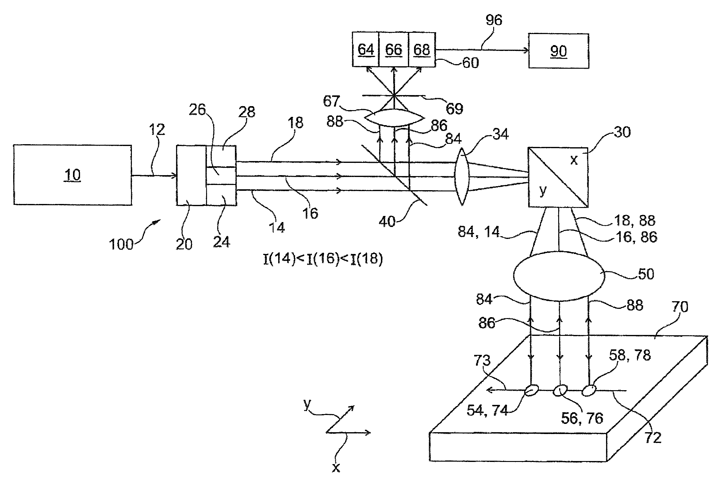
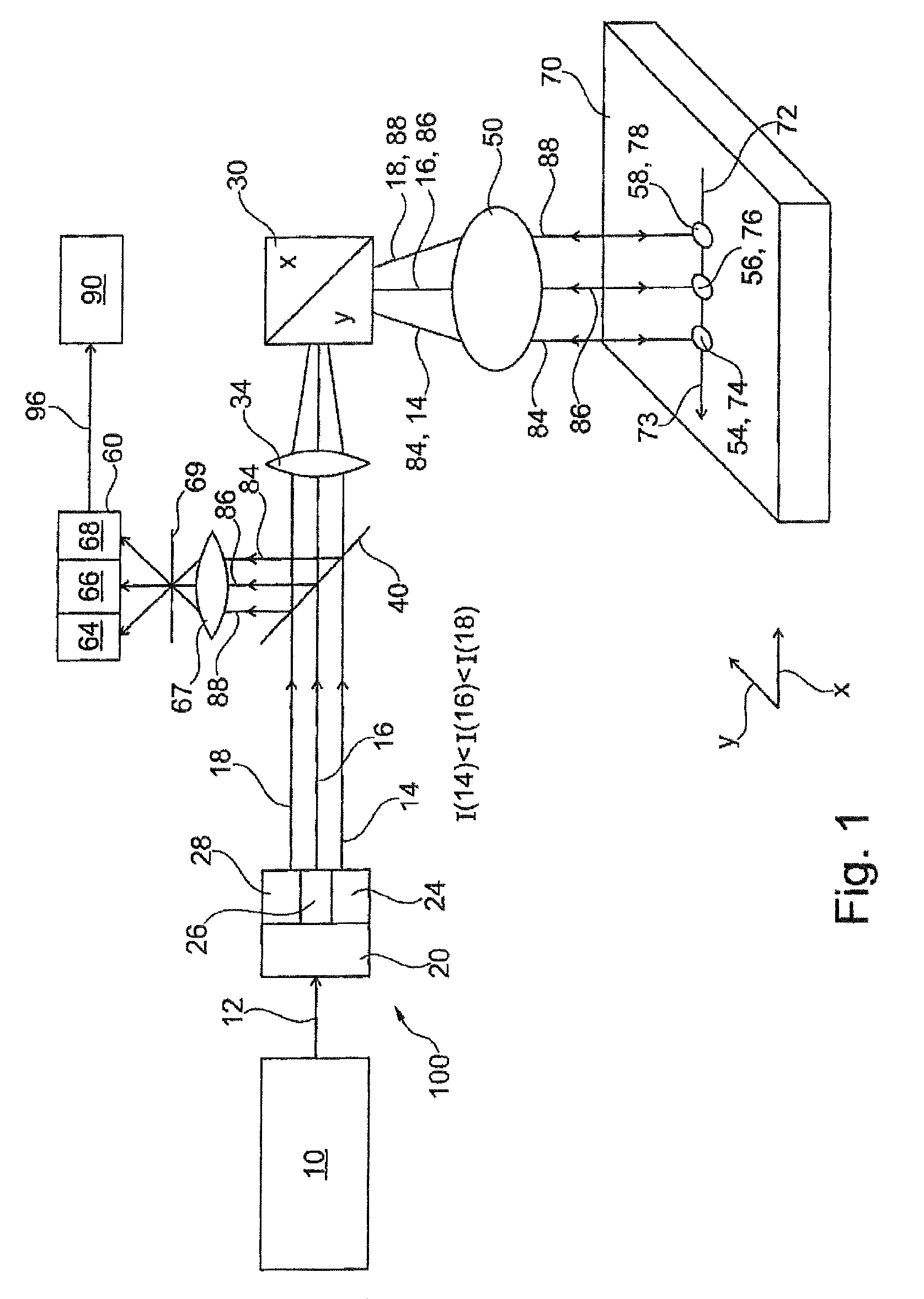
[0040]A first embodiment of a method according to the invention and of a scanning microscope 100 according to the invention is explained with reference to FIG. 1. A light source 10, in particular a laser, for emitting excitation light 12, optical means (20, 30, 40, 50) and also a detector unit 60 are shown therein as essential components.

[0041]As part of the optical means, firstly an optical separating device 20 is present, which separates the excitation light 12 into a plurality of illumination beams (14, 16, 18), wherein the illumination beams (14, 16, 18) serve for generating a plurality of different illumination spots (54, 56, 58) on a specimen 70.

[0042]A further component part of the optical means is a main chromatic splitter 40, through which the illumination beams (14, 16, 18) pass. Thereafter, the illumination beams (14, 16, 18) pass via an optical unit 34 onto a scanning device 30, by which they are scanned over the specimen 70 according to the invention such that the illum...


PUM


Abstract

The invention relates to a method for scanning microscopy wherein a specimen is scanned simultaneously with a plurality of illumination spots of an excitation light. The light emitted by one specimen location irradiated with one illumination spot is detected independently of the light emitted by another specimen location illuminated with another illumination spot. A microscopic image of the specimen can be compiled from the emitted light detected for the different specimen locations. The method provides that the intensities of the different illumination spots are set independently of one another, and in that the illumination spots are guided over the specimen one after another in a scan line. The invention additionally relates to a scanning microscope.

Description

CROSS REFERENCE TO RELATED APPLICATIONS[0001]This application is a continuation application of international patent application PCT / EP2014 / 078202, filed Dec. 17, 2014, and claiming priority from German application 10 2013 021 482.3, filed Dec. 17, 2013, and the entire content of both applications is incorporated herein by reference.FIELD OF THE INVENTION[0002]The present invention relates to a method for scanning microscopy and to a scanning microscope.BACKGROUND OF THE INVENTION[0003]In a method of the generic type, a specimen is scanned simultaneously with a plurality of illumination spots of an excitation light, and the light emitted by one specimen location irradiated with one illumination spot is detected independently of the light emitted by another specimen location illuminated with another illumination spot. A microscopic image of the specimen can be compiled from the emitted light detected for the different specimen locations.[0004]A scanning microscope of the generic type ...

Claims


Application Information

Patent Timeline
IPC IPC(8): G02B21/00G02B21/36
CPCG02B21/0032G02B21/0076G02B21/008G02B21/367G02B21/002G02B21/004
Inventor EGGERT, HELGEHILBERT, MICHAEL
Owner CARL ZEISS MICROSCOPY GMBH
Why Eureka
Try Eureka