
Systems, methods and devices for deriving subscriber and device identifiers in a communication network

a communication network and subscriber technology, applied in the field of network analytics, can solve the problems of ue tracking, device analytics, network operators, and overall network analytics, and achieve the effect of facilitating network analytics

Active Publication Date: 2016-10-06
NETSCOUT SYST TEXAS LLC
View PDF5 Cites 39 Cited by
  • Summary
  • Abstract
  • Description
  • Claims
  • Application Information

AI Technical Summary

Benefits of technology

The patent text describes a technique called network analytics that can analyze data messages in a network and map them to a specific device. This helps to identify and track the device throughout the network. The technique is useful for improving network penetration and protecting data security.

Problems solved by technology

Despite the desirable intentions of such improved security features (e.g., protecting UE information against unwanted interception, etc.), such LTE security features hinder valuable network analytics such as device analytics, UE tracking, and the like, for network operators.
That is, without appropriate identifiers (e.g., subscriber identifiers, equipment identifiers, etc.) to correlate and assign traffic amongst various network nodes to particular calls, sessions, devices, users, etc., overall network analytics, including UE tracking, prove difficult at best.
Some conventional approaches attempt to bypass such security features by soliciting information from certain network nodes (e.g., a Mobile Management Entity node); however, not all MME vendors allow or even support such solicitation.

Method used


Image

  • Systems, methods and devices for deriving subscriber and device identifiers in a communication network
  • Systems, methods and devices for deriving subscriber and device identifiers in a communication network
  • Systems, methods and devices for deriving subscriber and device identifiers in a communication network

Examples


Embodiment Construction

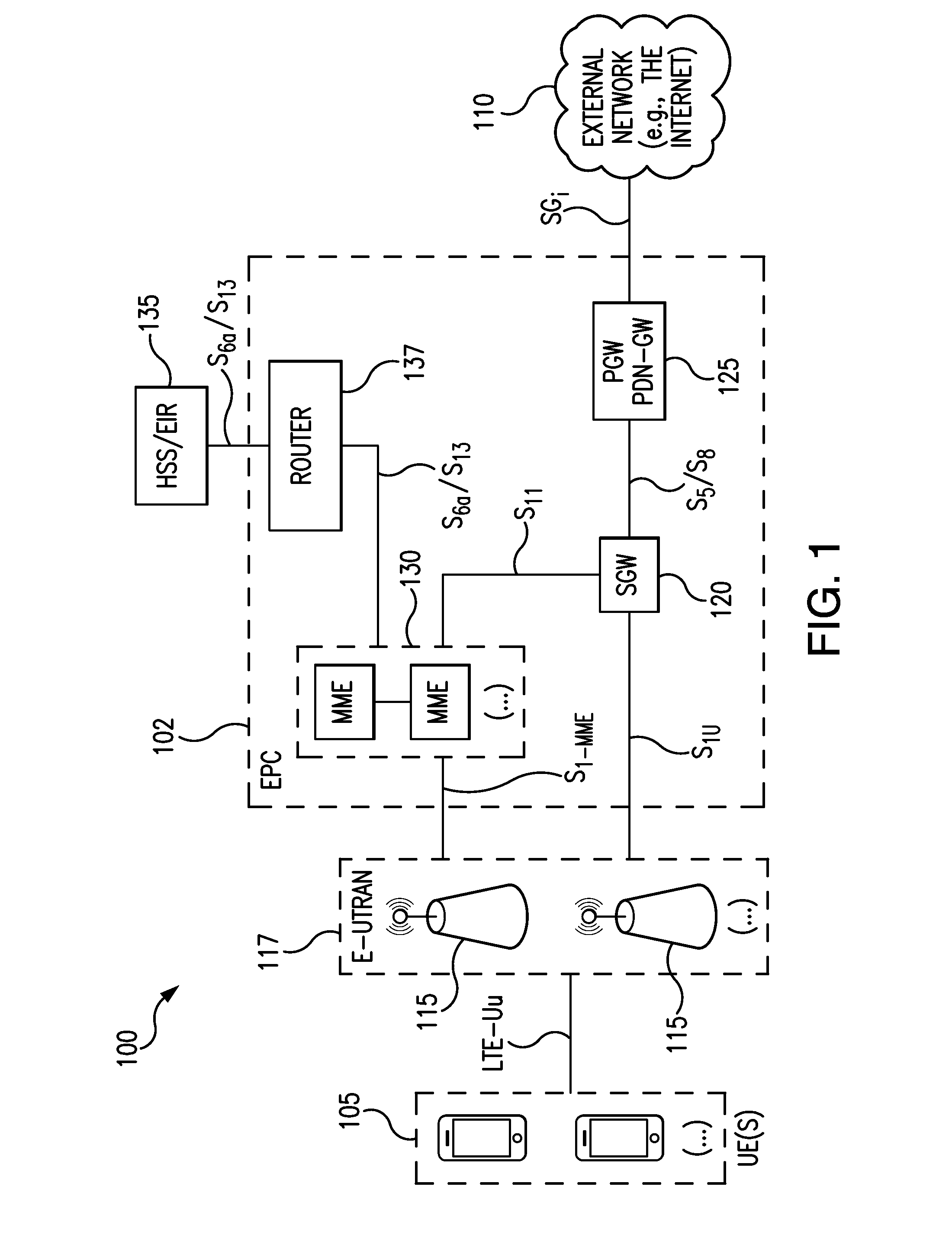
[0028]As discussed above, the 3rd Generation Partnership Project (3GPP) organization specifies the architecture for various mobile cellular networks. The latest mobile Long Term Evolution (LTE) network architecture defined by the 3GPP is called Evolved 3GPP Packet Switched Domain—also known as the Evolved Packet Core (EPC).

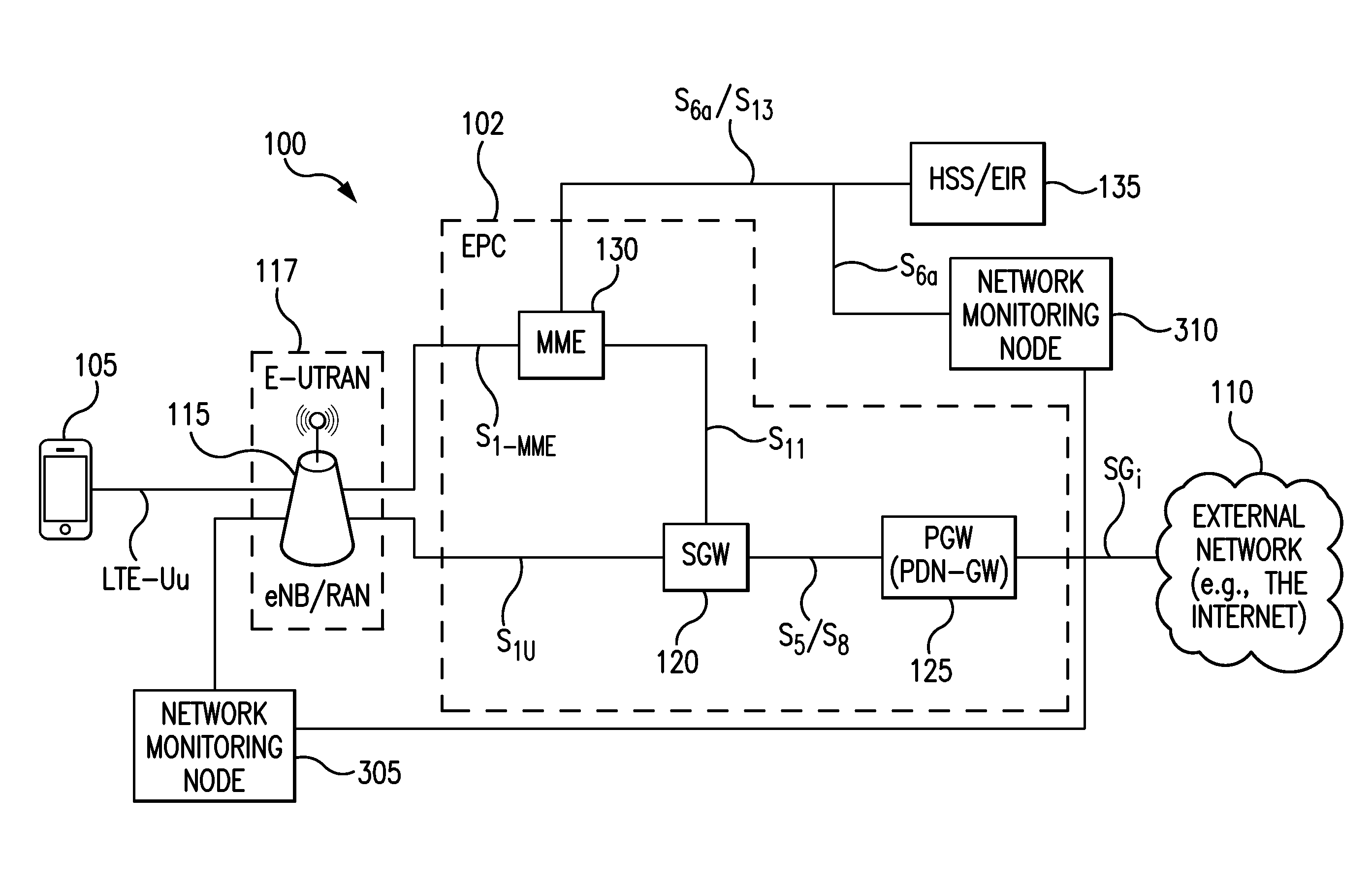
[0029]FIG. 1 is a diagram illustrating an LTE network architecture 100. The LTE network architecture 100 may be referred to as an Evolved Packet System (EPS) 100. The EPS 100 may include one or more user equipment (UE) 105, an Evolved UMTS Terrestrial Radio Access Network (E-UTRAN) 117, including one or more Evolved Node B(s) 115 (eNBs), an Evolved Packet Core (EPC) 102, a Home Subscriber Server (HSS) 135, and an External Network 110, (e.g., the Internet). As shown in FIG. 3, an S6a / S13 interface is preferably provided between HSS / EIR 135 and MME 130. It is noted that in an illustrated embodiment, the EIR functionality is expected to be built into the HSS.

[0030]EP...


PUM


Abstract

A network monitoring node receives one or more data messages regarding User Equipment (UE) from one or more network interfaces for a communication session in the communication network continuously in real-time, determines a subscriber identification (ID) associated with the UE from the one or more data messages regarding the UE, and determines an equipment identification (ID) associated with the UE from the one or more data messages regarding the UE. The network monitoring node further receives a base-key associated with the UE from the one or more data messages regarding the UE, derives a decryption key from the base-key, decrypts a temporary ID associated with the UE from the one or more data messages regarding the UE based on the decryption key, maps the temporary ID with the subscriber ID for the UE, and the subscriber ID with the equipment ID for the UE, and assigns data messages for all further communication sessions to the UE based on the mapping. The Subscriber ID and Equipment ID are preferably assigned to all further communication sessions for that UE. It updates the mapping when changes to the temporary ID or equipment ID occur.

Description

BACKGROUND[0001]1. Field of the Invention[0002]The present disclosure relates to network analytics, and more particularly, to deriving subscriber and device identifiers of User Equipment (UE) in communication networks.[0003]2. Description of the Related Art[0004]Long Term Evolution (LTE) networks generally use 4th generation (4G) wireless technologies and are considered a next evolution for GSM (Global System for Mobile Communications). LTE particularly provides a set of enhancements to the Universal Mobile Telecommunications System (UMTS) mobile standard promulgated by Third Generation Partnership Project (3GPP), and is designed to provide higher data transmission rates while efficiently utilizing the spectrum thereby supporting a multitude of subscribers. LTE is all-IP permitting applications such as real time voice, video, gaming, social networking and location-based services.[0005]LTE networks also provide improved security features that, in part, protect User Equipment (UE) ide...

Claims


Application Information

Patent Timeline
Patent Type & Authority Applications(United States)
IPC IPC(8): H04W8/26H04W4/12H04W8/02H04W12/04H04W8/20
CPCH04W8/26H04W12/04H04W8/205H04W88/08H04W4/12H04W88/02H04W8/02H04W12/06H04W24/08H04W12/03H04W12/75H04W12/71H04W12/72H04W12/02
Inventor KETHEESAN, KANAPATHIPILLAISURESH, KIRAN B.
Owner NETSCOUT SYST TEXAS LLC
Learn More