Method for the operation of wind power plants

a technology for wind power plants and wind turbines, applied in wind energy generation, motors, electrical equipment, etc., can solve problems such as creating idle power, and achieve the effects of high idle power, high potential effective power output, and high idle power

Active Publication Date: 2008-02-21
NORDEX ENERGY SE & CO KG
View PDF10 Cites 11 Cited by
  • Summary
  • Abstract
  • Description
  • Claims
  • Application Information

AI Technical Summary

Benefits of technology

[0016]The method ensures that a high idle power can be made available even in the case of favorable wind conditions and a correspondingly high potential effective power output. The demand of network operators to provide a high idle power can be achieved in this manner. Moreover, several wind power plants or wind farms can be connected to weaker networks, since the highly available idle power ensures a larger contribution to the network stability.
[0017]Particularly advantageous with respect to the method known from DE 103 44 392 A1, the entire contents of which is incorporated herein by reference, is that a minimum and a maximum idle power are assigned to each value of the effective power. These idle power values are directly available and can be forwarded, for example, to improve the network management to a power company, which thus receives an overview of the available idle power reserve, which can be accessed without losses in effective power.
[0022]In another preferred embodiment of the invention, the minimum idle power and the maximum idle power for each effective power are calculated from the permissible current carrying capacity of the stator and rotor coils of the generator of the wind power plant. The current carrying capacity of the individual components can thereby be dependent on other parameters. As already explained above, the available cooling capacity and / or the environmental temperature can be taken in consideration in particular in order to avoid a thermal overload. The cooling capacity can in turn depend on the amount of wind and the effective power. The current carrying capacity of the named coils represents an important upper limit for the current carrying capacity of the entire wind power plant. It is thereby ensured that the stator and rotor coils of the generator are not overloaded.

Problems solved by technology

In the case of the operation of wind power plants, it is known to also create idle power in addition to the effective power that is important for energy generation.

Method used


Image

  • Method for the operation of wind power plants
  • Method for the operation of wind power plants
  • Method for the operation of wind power plants

Examples


Embodiment Construction

[0028]While this invention may be embodied in many different forms, there are described in detail herein a specific preferred embodiment of the invention. This description is an exemplification of the principles of the invention and is not intended to limit the invention to the particular embodiment illustrated.

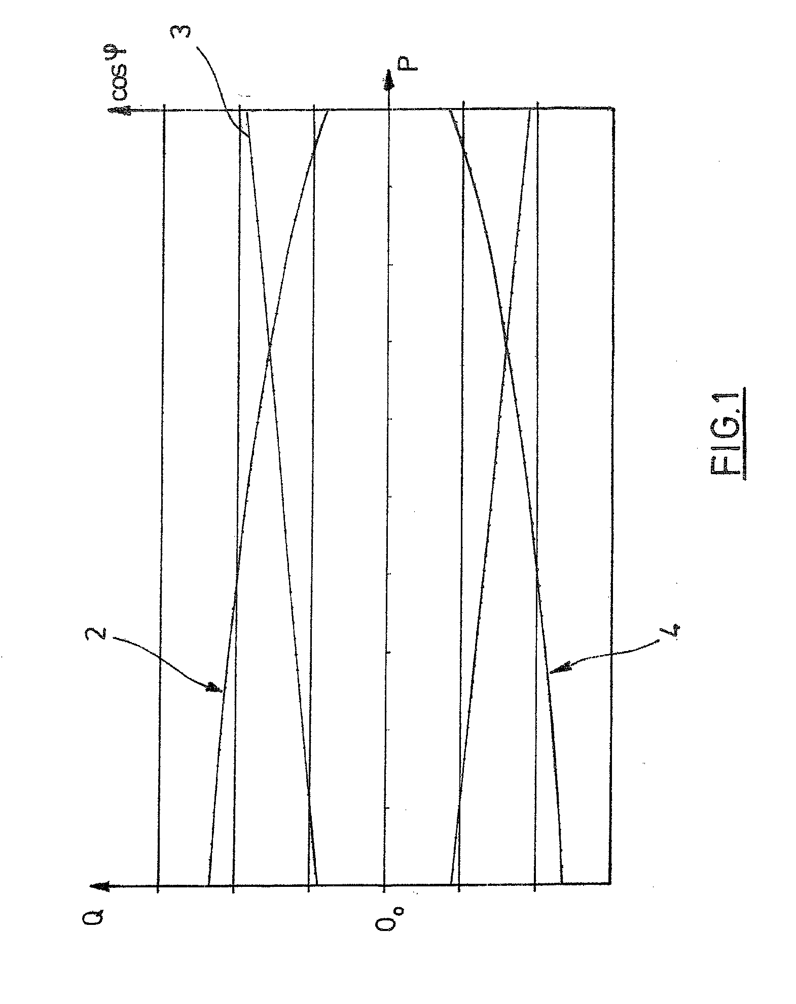
[0029]FIG. 1 shows the connection between the idle power Q and effective power P.

[0030]The effective power P is shown on the abscissa. The shown effective power range begins at zero and extends up to a maximum effective power, which may exceed the nominal power of the wind power plant by a certain amount. On the ordinate, a maximum idle power Q (curve 2) and a minimum idle power Q (curve 4) are assigned to each effective power P. The amounts of the minimum and maximum idle powers assigned to a certain effective power value in curves 2 and 4 correspond with a specified or registered idle power, which corresponds with a capacitive or inductive idle power. The amounts must not b...


PUM


Abstract

Method for the operation of a wind power plant with controllable effective power, wherein an idle power interval defined by a minimum idle power and a maximum idle power is assigned to each value of the effective power and the actual idle power can be controlled within this interval, characterized in that the effective power is reduced when a target idle power lies outside of the idle power interval assigned to the current effective power.

Description

CROSS-REFERENCE TO RELATED APPLICATIONS[0001]Not applicable.STATEMENT REGARDING FEDERALLY SPONSORED RESEARCH[0002]Not applicable.BACKGROUND OF THE INVENTION[0003]The invention relates to a method for the operation of wind power plants, more specifically to a method for the operation of a wind power plant with controllable effective power, wherein an idle power interval is assigned to each effective power and the delivered idle power within this idle power interval is controllable[0004]In the case of the operation of wind power plants, it is known to also create idle power in addition to the effective power that is important for energy generation. The idle power can on one hand serve to compensate an idle resistance generated by individual components of the wind power plant in order not to load a mains power supply coupled with the wind power plant. Additionally, a support of the voltage of the mains power supply can also be achieved through a targeted allocation of idle power, Norma...

Claims


Application Information

Patent Timeline
Patent Type & Authority Applications(United States)
IPC IPC(8): H02P9/02F03D9/00
CPCF03D7/0272F03D7/028F03D7/042H02J3/386H02J3/1892Y02E10/723Y02E10/763F03D9/003F03D9/255H02J2300/28H02J3/381Y02E10/72Y02E10/76
Inventor RICHTER, KAYWOLDMANN, THOMAS PAULJURKAT, MARK
Owner NORDEX ENERGY SE & CO KG
Why Eureka
Try Eureka