
Smart card battery charging during card use

a smart card and battery technology, applied in the field of smart cards, can solve the problems of affecting the battery life of the smart card, the inability to embed large power sources (such as large batteries) in the smart card, and the inability to charge the smart card dynamically

Active Publication Date: 2016-10-06
PAYPAL INC
View PDF1 Cites 6 Cited by
  • Summary
  • Abstract
  • Description
  • Claims
  • Application Information

AI Technical Summary

Benefits of technology

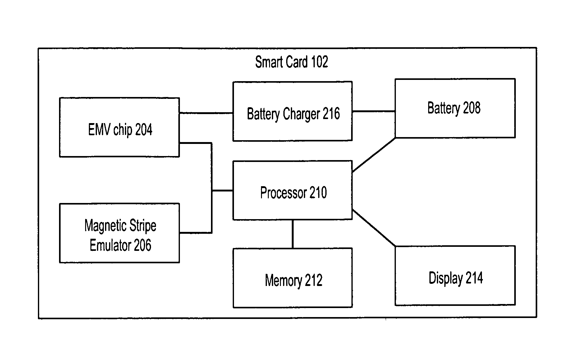
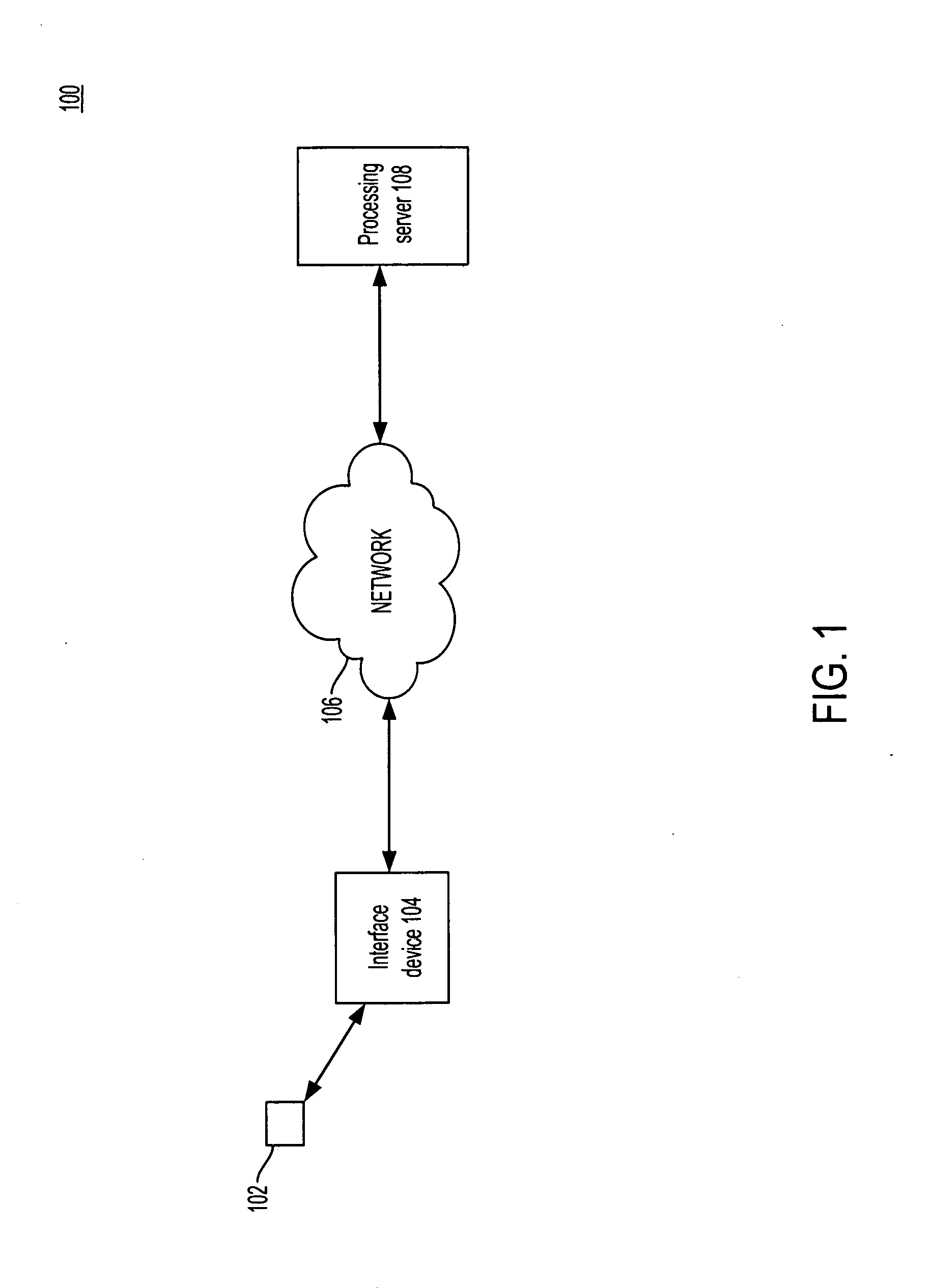
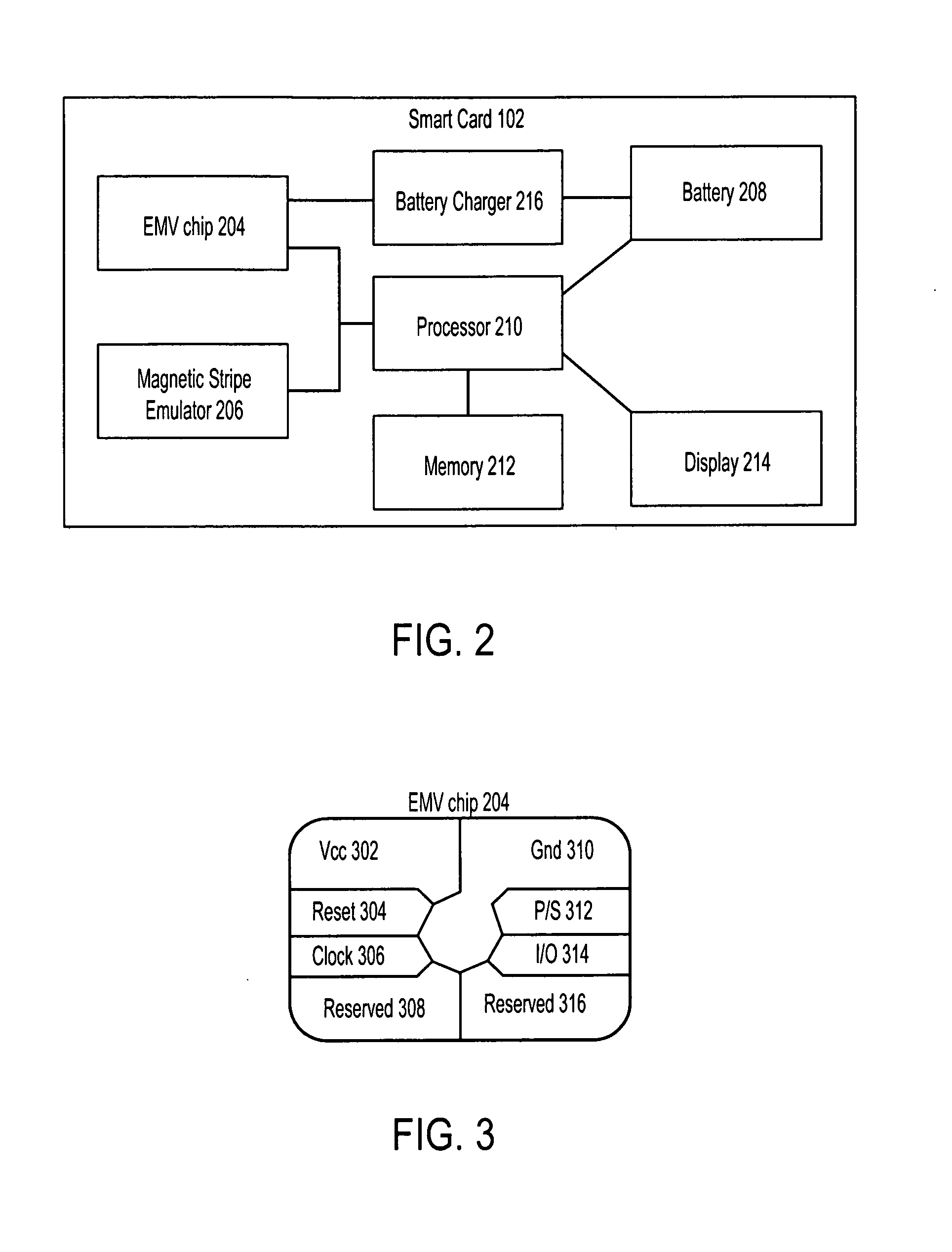
The present patent relates to a system and method for dynamically charging the battery of a smart card from an interface device, such as a point of sale terminal or EMV reader. The smart card detects the interface device and determines if it is pre-arranged to charge the card. If it is, the smart card charges the battery without needing additional regulation of the voltage. This allows the battery life of the card to be extended, as it does not need to be re-charged frequently. The technical effect of this patent is to improve the functionality and convenience of smart cards by incorporating a power source within the card, without requiring the user to also carry a charger for the card.

Problems solved by technology

However these smart cards generally do not have an embedded battery source.
Given the size limitations of the smart cards, it is not possible to embed large power sources (such as large batteries) in the smart cards.
With ever-increasing electronics and specified size constraints, the battery life of the smart card becomes a bottleneck.
This bottleneck leads to frequent re-charging of the battery and a corresponding inconvenience to the user and lack of utility for the smart card, since continued use of the smart card with integrated battery would require the user to also carry a charger for the smart card, so as to retain use and utility of the smart card.

Method used


Image

  • Smart card battery charging during card use
  • Smart card battery charging during card use
  • Smart card battery charging during card use

Examples


Embodiment Construction

[0015]The detailed description set forth below, in connection with the appended drawings, is intended as a description of various configurations and is not intended to represent the only configurations in which the concepts described herein may be practiced. The detailed description includes specific details for the purpose of providing a thorough understanding of the various concepts. However, it will be apparent to those skilled in the art that these concepts may be practiced without these specific details. In some instances, well-known structures and components are shown in block diagram form in order to avoid obscuring such concepts.

[0016]The present disclosure provides systems, methods, and computer program products for dynamically charging the internal battery of a smart card from an interface device (such as a point of sale terminal) so that the battery life of the smart card may be extended. In an embodiment, a smart card device detects that it has interfaced with an interfa...


PUM


Abstract

Systems, methods, and computer program products are disclosed for dynamically charging an internal battery of a smart card from an interface device (such as a terminal) so that the battery life may be extended. A smart card device detects that it has interfaced with an interface device and that voltage is now being provided to the smart card device. The smart card device may divert some or most of the current being provided with the voltage to charge an internal battery of the smart card device, either concurrent to other communications between the smart card device and the interface device or before / after relevant communications are completed. As a result, the use of a smart card device contributes to the charge of the smart card device's internal battery, instead of draining it.

Description

CROSS-REFERENCE TO RELATED APPLICATIONS[0001]The present application claims priority to and the benefit of the U.S. Provisional Patent Application No. 62 / 140,707, filed Mar. 31, 2015, which is hereby incorporated by reference in its entirety.BACKGROUND[0002]1. Field of the Invention[0003]The present disclosure generally relates to smart cards with built-in electronics, and more particularly to the dynamic charging of a smart card's battery during card use.[0004]2. Related Art[0005]Smart cards include a processor embedded in the card, which stores encrypted data. A common processor is an EMV (Euro, Mastercard, Visa) integrated circuit (“EMV chip”). However these smart cards generally do not have an embedded battery source. Instead, when the smart card is inserted into an interface device (such as an EMV reader), the contacts on the EMV chip make contact with the connectors on the EMV reader. The EMV reader, which has a power source, supplies power to the EMV chip and then reads the d...

Claims


Application Information

Patent Timeline
IPC IPC(8): H04B1/3883H04L12/26H04W52/02
CPCH04B1/3883H04L43/16H04W52/0267H04W52/0261Y02D30/70
Inventor PAHUJA, ANUPAM
Owner PAYPAL INC
Learn More