
Decoding method of low density parity check code and information storing method in the decoding method

a low density parity and decoding method technology, applied in the field of decoding methods of low density parity check codes, can solve the problems of limiting the application of ldpc codes to some communication systems and storage apparatuses, ultra-low bit error rate, and inability to provide enough decoding messages to correctly decode, so as to reduce the storage space and hardware costs. , the effect of reducing the necessary storage spa

Inactive Publication Date: 2016-10-06
NATIONAL TSING HUA UNIVERSITY
View PDF7 Cites 9 Cited by
  • Summary
  • Abstract
  • Description
  • Claims
  • Application Information

AI Technical Summary

Benefits of technology

The present patent text describes a method for efficiently detecting and correcting errors in data transmission using a type of code called LDPC. The method reduces the amount of storage space and hardware required for the code, and also uses a technique called isomorphism to further decrease the amount of data needed. This results in a more efficient and cost-effective system for error correction.

Problems solved by technology

However, the error-flooring phenomenon limits the LDPC codes to be applied to some communication systems and storage apparatuses which require the ultra-low bit error rate.
Unfortunately, some variable nodes and check nodes in Tanner graph may form the trapping sets.
In the trapping sets, all variable nodes are in error, but most of the check nodes are mis-satisfied and cannot provide enough decoding messages to correctly decode the received vector.
Thus, the large storage space is needed, and the hardware cost is increased.
In addition, if the location information of the variable nodes and the check nodes in one trapping set is not recorded, and the errors exist in the check nodes of the trapping set, the propose solution may not correct errors successfully.
However, the above other one proposed solution needs longer decoding time.

Method used


Image

  • Decoding method of low density parity check code and information storing method in the decoding method
  • Decoding method of low density parity check code and information storing method in the decoding method
  • Decoding method of low density parity check code and information storing method in the decoding method

Examples


Embodiment Construction

[0024]Reference will now be made in detail to the exemplary embodiments of the present disclosure, examples of which are illustrated in the accompanying drawings. Wherever possible, the same reference numbers are used in the drawings and the description to refer to the same or similar parts.

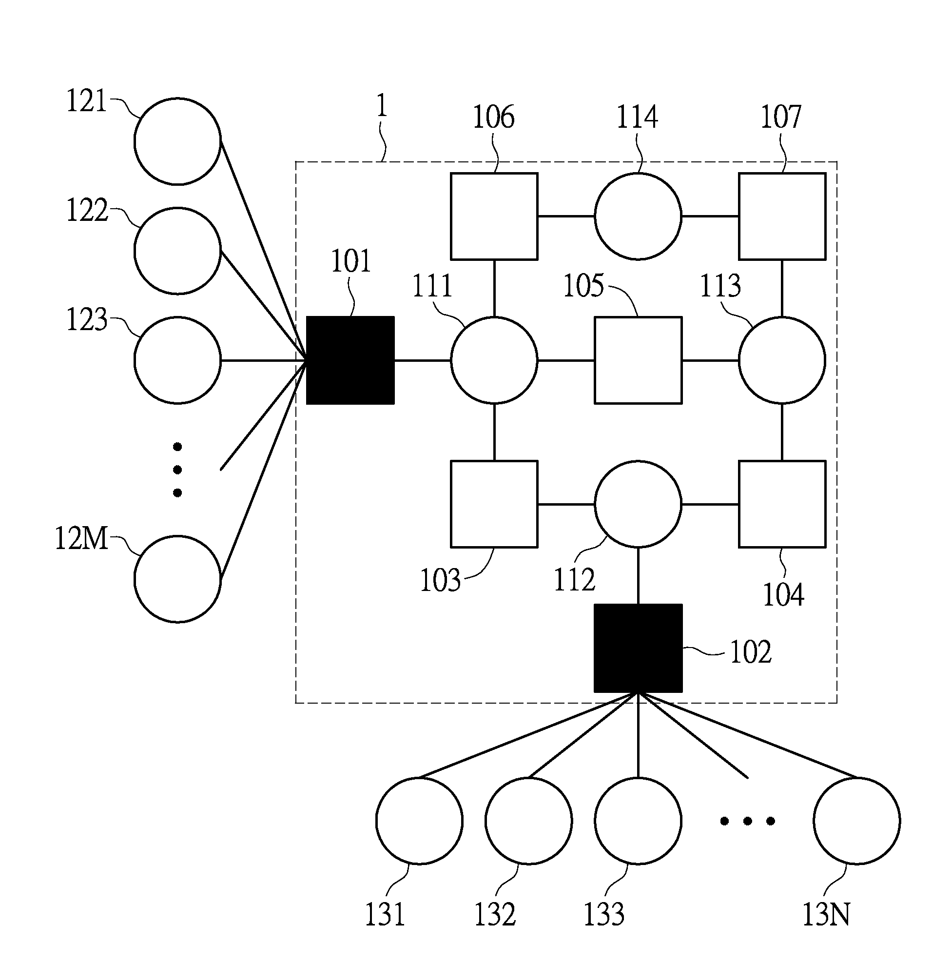
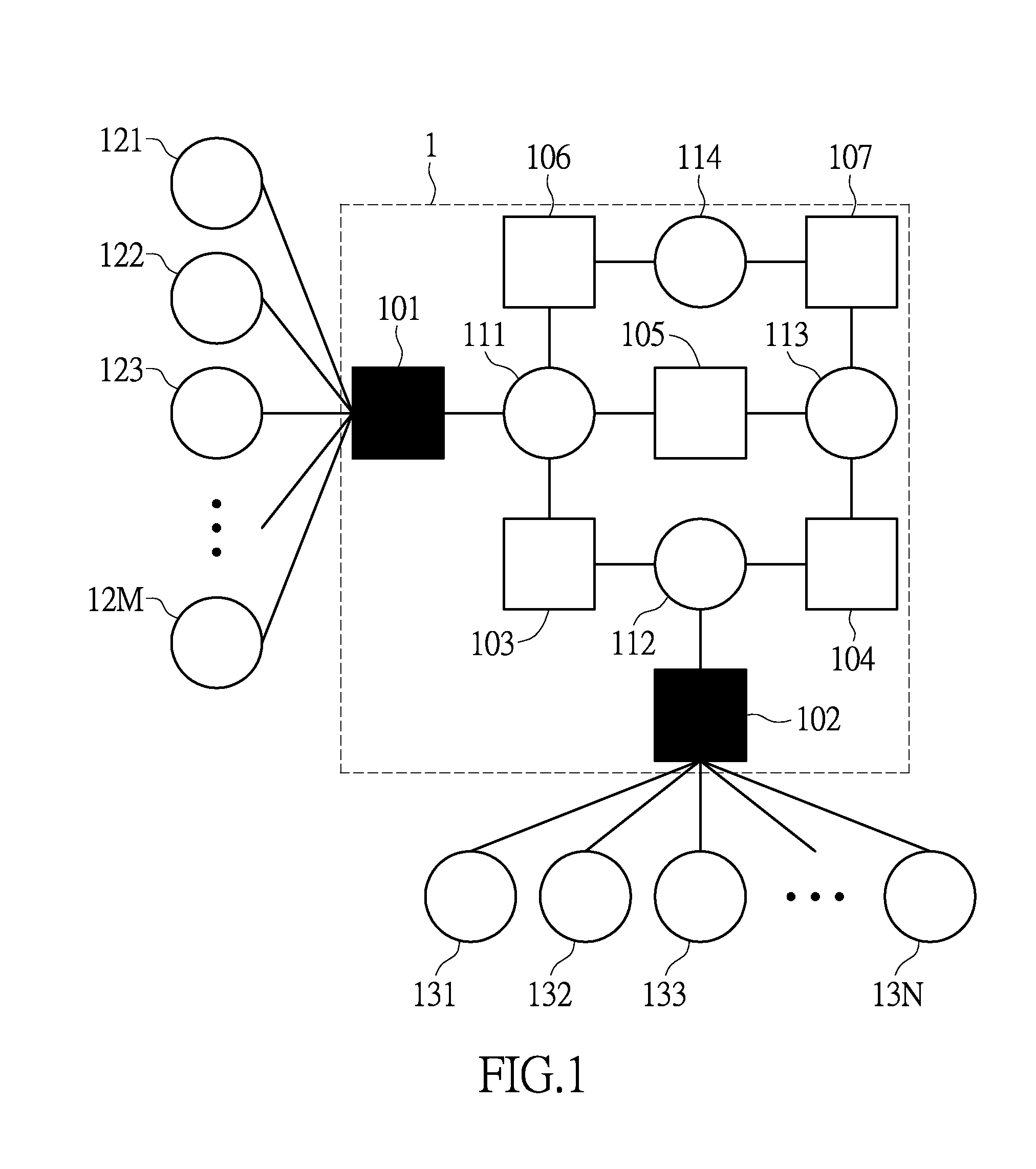
[0025]Referring to FIG. 1, FIG. 1 is a schematic diagram of the (4, 2) trapping set according to an exemplary embodiment of the present disclosure. The (4, 2) trapping set 1 is formed by a plurality of check nodes 101 through 107 and a plurality of variable nodes 111 through 114, wherein the notation (4, 2) means the (4, 2) trapping set 1 has two unsatisfied check node 101, 102 and 4 variable nodes 111 through 114.

[0026]In FIG. 1, the unsatisfied check node 101 is connected to the variable nodes 111 and the variable nodes 121 through 12M outside the (4, 2) trapping set 1, and the unsatisfied check node 102 is connected to the variable node 112 and the variable nodes 131 through 13N outside the (4...


PUM


Abstract

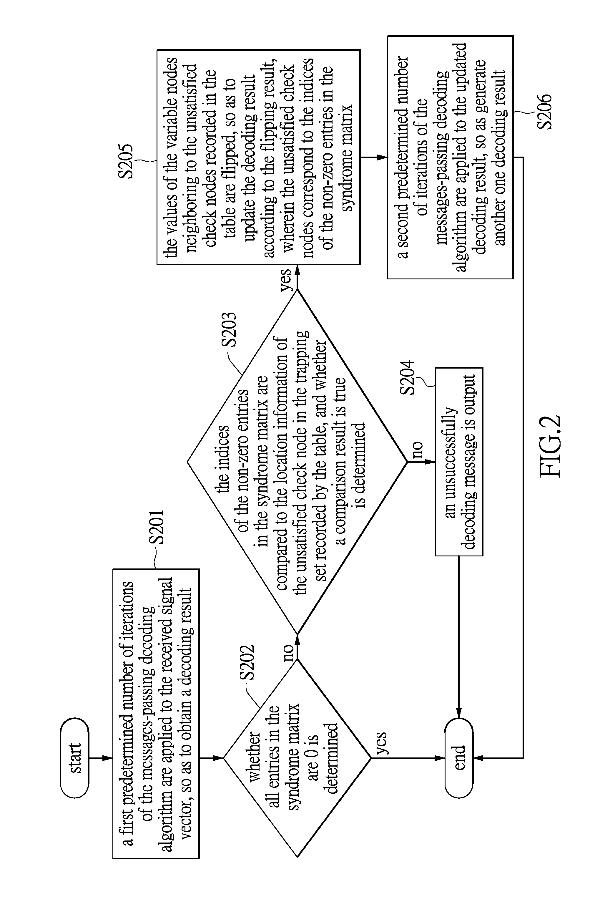
A decoding method of a LDPC comprises following steps. A first predetermined number of iterations of a messages-passing decoding algorithm are applied to a received signal vector, so as to attempt to decode a transmitted (or stored) codeword. Whether the decoding result converges to a valid codeword is determined by observing whether the decoding result makes all check nodes satisfied or not. When the decoding result does not converge to a valid codeword, the value of at least one of the variable nodes neighboring to one of the un-satisfied check node is be adjusted to a non-zero value, wherein the selected variable node is included in a trapping set. Then, a second predetermined number of iterations of the messages-passing decoding algorithm are applied to the updated decoding result to generate another one decoding result, and whether the other one decoding result converges to a valid codeword is checked.

Description

BACKGROUND[0001]1. Technical Field[0002]The instant disclosure relates to a decoding method of a Low Density Parity Check (LDPC) code; more particularly, to a decoding method of LDPC code which can reduce the necessary storage space and an information storing method using in the decoding method.[0003]2. Description of Related Art[0004]The LDPC code performs excellently in the water-fall region, and even can have a channel capacity approaching Shannon limitation. Since the LDPC code has the outstanding performance, a large number of standards (such as DVB-S2 / T2 / C2 / H, IEEE802.3an, IEEE802.16e, IEEE802.11ac) adopt the LDPC code, and even the storage apparatuses utilize the LDPC code for error correction.[0005]However, the error-flooring phenomenon limits the LDPC codes to be applied to some communication systems and storage apparatuses which require the ultra-low bit error rate. The error-flooring phenomenon is caused by that the trapping sets formed by some specific structures of Tann...

Claims


Application Information

Patent Timeline
Patent Type & Authority Applications(United States)
IPC IPC(8): H03M13/11
CPCH03M13/1128H03M13/1117H03M13/1108H03M13/1111H03M13/1142H03M13/116H03M13/3715H03M13/6502
Inventor HSIEH, CHIEH-SHENLEE, HUANG-CHANGUENG, YEONG-LUH
Owner NATIONAL TSING HUA UNIVERSITY
Learn More