
Method and apparatus for monitoring changes in road surface condition

a technology for analyzing paved surfaces and images, applied in the field of methods and means for monitoring the condition of paved surfaces, can solve the problems of inability to detect the type and severity of surface defects, and inability to use the same method for different types of paved surfaces

Inactive Publication Date: 2016-10-06
D VISION C V S LTD
View PDF4 Cites 29 Cited by
  • Summary
  • Abstract
  • Description
  • Claims
  • Application Information

AI Technical Summary

Benefits of technology

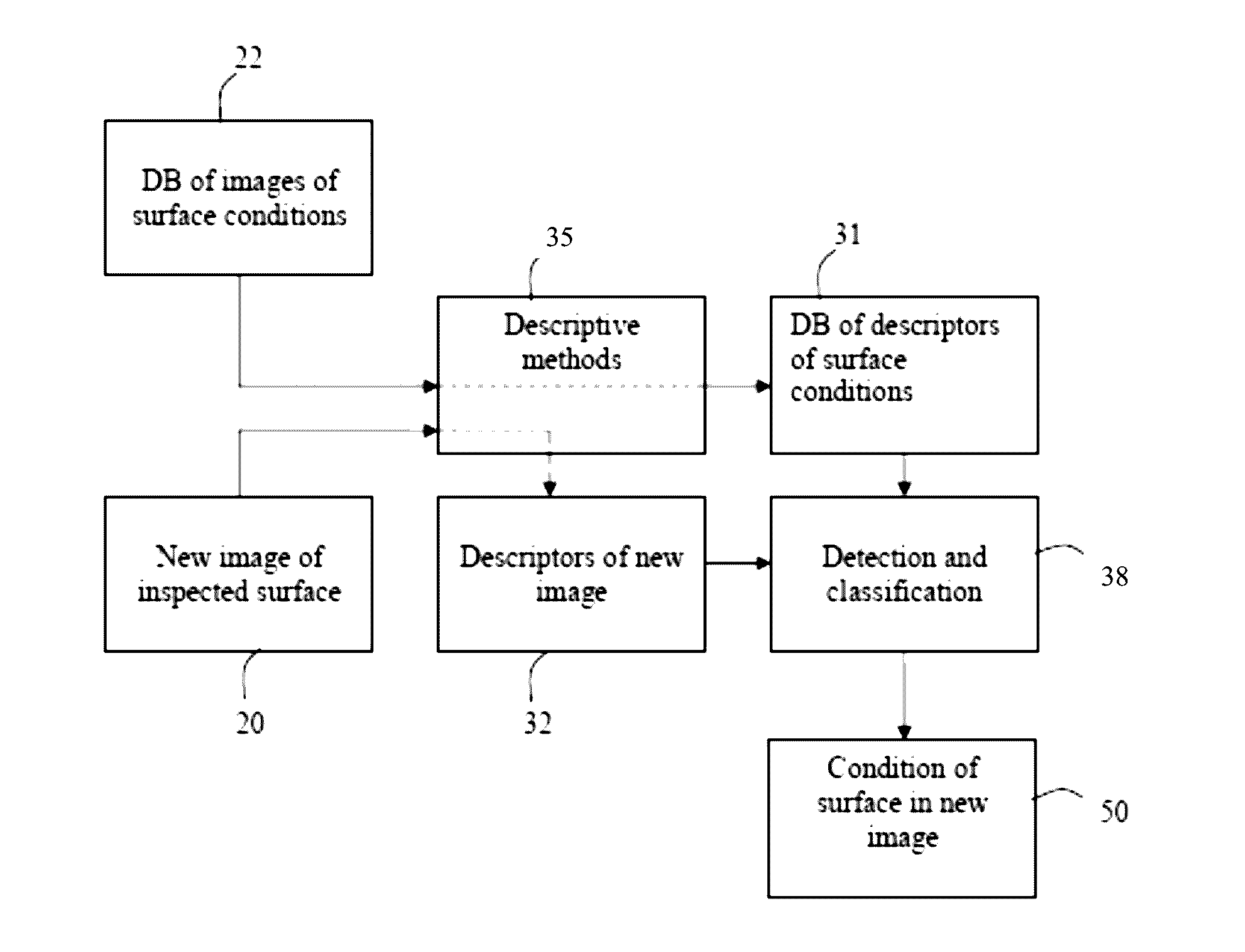
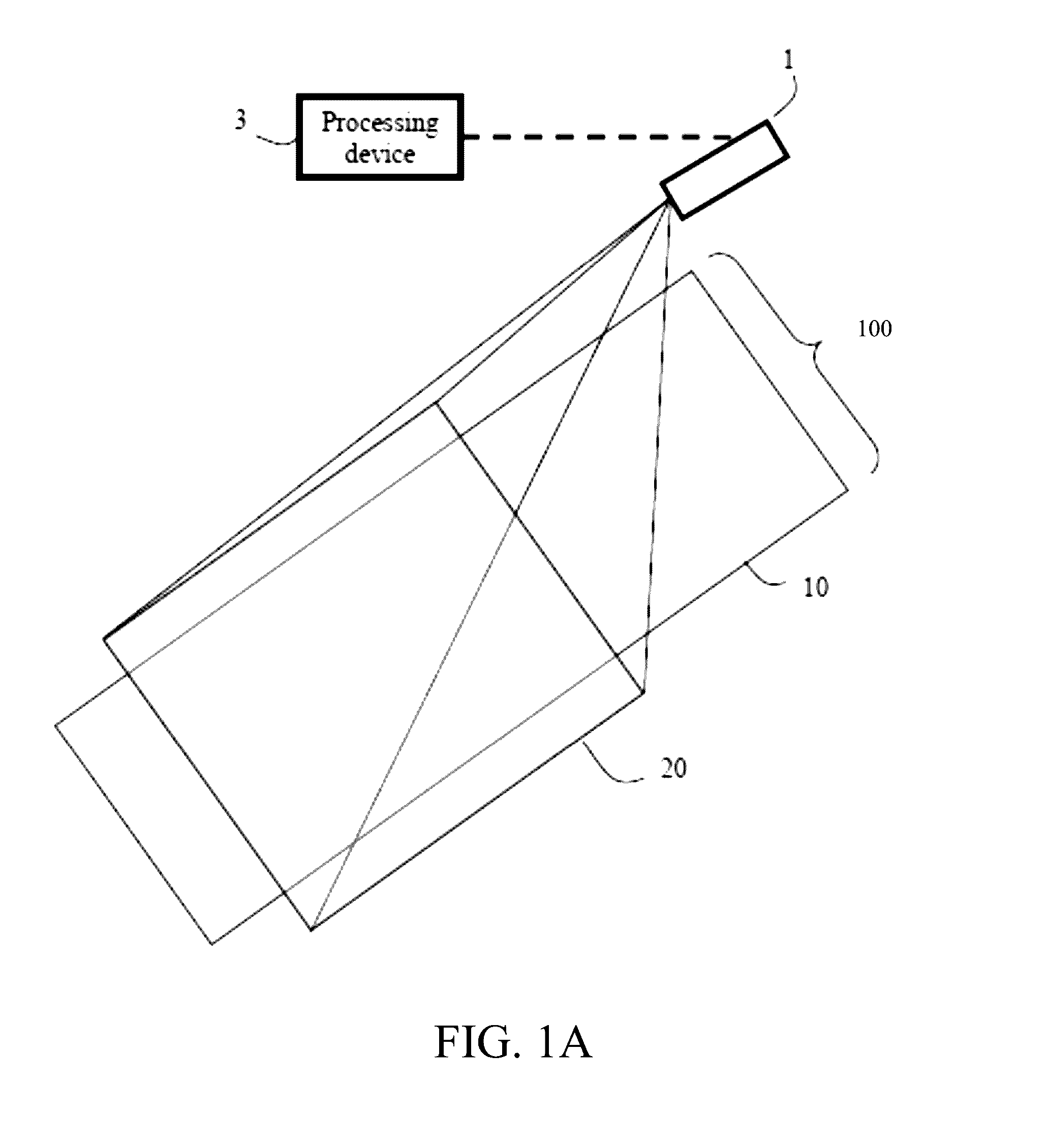
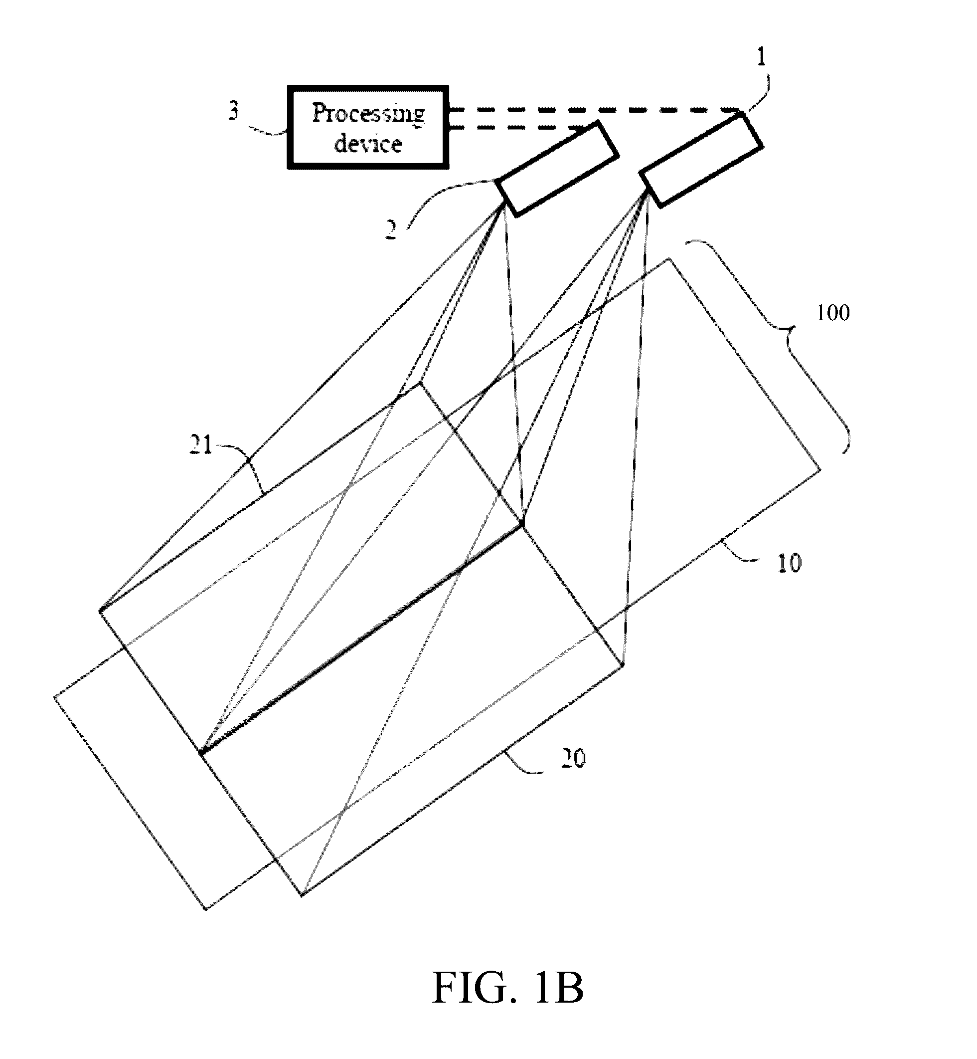
The invention is a system and method for detecting and classifying defects in paved surfaces using machine learning techniques. The system includes an imaging device mounted on a vehicle and a processing and storage device in data communication with the imaging device. The imaging device obtains images of the paved surface and the processing and storage device performs three-dimensional reconstructions of overlapping areas of the images. The system can detect and classify defects based on the shape, color, or gray levels of the images. The method involves training a database of descriptors of distinct features of surface conditions in images of paved surfaces with known surface conditions and comparing the descriptors to images of the paved surface obtained from the system. The system can also use a laser range finder or a geolocation device to map the position of the paved surface and calculate the coordinates of the absolute location of the system. The invention provides a more efficient, automated, and accurate method for detecting and classifying defects in paved surfaces.

Problems solved by technology

Paved surfaces such as roads, runways, parking lots, and the like are inherently subject to heavy wear from traffic and degradation from weather conditions and ground movements.
These human evaluation procedures are very time consuming and labor intensive and are inherently inaccurate, unreliable and irreproducible.
Development of automated systems and methods for analyzing the paved surface or images thereof in order to detect the type and severity of surface defects remains a very challenging task.
Yet even in systems that attempt to overcome this difficulty by the use of artificial light, accurate and efficient detection and classification of all defects such as cracks and potholes remains difficult, because the colors (or gray levels) of the defects will vary from image to image depending on such factors as the type of imaging device used, the position of the imaging device relative to the defect, the position of the light source relative to the defect, the type of asphalt or concrete used, depth of the crack, whether a given crack is filled (by sand for example) or not, and so on.
Lighting equipment that can provide the requisite level of illumination is expensive, heavy and complex, and requires the use of large power supplies and therefore frequently requires the use of specially designated vehicles to carry and operate it as well.
A small number of devices that are designed to perform automatic detection and classification of defects in paved surfaces are known in the art, but these devices suffer from the opposite problem of being too simple to be used in practice.
Moreover, this system is quite cumbersome, since it relies on the use of cameras mounted both at the front and at the back of the vehicle.
This system is mounted on the rear of a vehicle and is quite cumbersome.
Moreover, this system can only be used at night in order to avoid shadows and unpredictably varying daylight illumination conditions.
One major disadvantage of this configuration is that the angle between the strobe lights and the cameras cause significant non-uniformities in the images, because pavement areas that are closer to the strobe lights appear much brighter than those further away, creating a lighting gradient that reduces the quality of the images.
The major disadvantage of this system is the large amount of electricity (several kW) needed to power the system, necessitating the use of a dedicated generator.
The system is thus cumbersome, and moreover is unable to provide good shadow contrast in the images, especially in the case of longitudinal cracks.
None of the above mentioned inspection systems provides a compact and power-efficient assembly that can perform a rapid and accurate road surface inspection that is unaffected by changes in local light conditions.
Furthermore, it can only identify the cracks if they are darker than the surrounding surface, which is often not the case.
Furthermore, the method does not specify the threshold that is used to mark crack seeds or cracks, and indeed, the threshold is different for every image and every crack.
This method suffers not only from these limitations, but also requires the use of artificial lighting, adding expense and complexity to the system.
While the foregoing challenges in the development of methods and systems for automatic detection and classification of defects in paved surface have been recognized for many years, none of the proposed solutions known in the art has succeeded in producing a single device that can adequately addressing all of them.

Method used


Image

  • Method and apparatus for monitoring changes in road surface condition
  • Method and apparatus for monitoring changes in road surface condition
  • Method and apparatus for monitoring changes in road surface condition

Examples


Embodiment Construction

[0039]In the following description, various aspects of the invention will be described. For the purposes of explanation, specific details are set forth in order to provide a thorough understanding of the invention. It will be apparent to one skilled in the art that there are other embodiments of the invention that differ in details without affecting the essential nature thereof. Therefore the invention is not limited by that which is illustrated in the figure and described in the specification, but only as indicated in the accompanying claims, with the proper scope determined only by the broadest interpretation of said claims.

[0040]As used herein, the term “paved surface” refers to any surface covered with at least one layer of a solid paving material. Non-limiting examples of “paved surfaces” within the meaning of the term as used herein include paved roadways, bridge surfaces, parking lots, and airplane runways. Non-limiting examples of paving materials with which the surface may ...


PUM


Abstract

A method and system for detecting and classifying defects in a paved surface is disclosed. A sequence of images of the paved surface is obtained from at least one imaging device that can be mounted on a vehicle. The images are used to form a three-dimensional reconstruction. A machine learning process is used to train the system to recognize different kinds of defects and defect-free surfaces. Performing a pixel-by-pixel comparison of the images obtained for a particular paved surface with a database of images of surfaces with known defects provides a determination of the locations of defects in that paved surface. The system and method disclosed herein do not require the use of artificial lighting and are unaffected by transient changes in ambient light.

Description

REFERENCE TO RELATED PUBLICATIONS[0001]This application claims priority from U.S. Provisional Pat. Appl. No. 62 / 177954, filed 30 Mar. 2015, and from U.S. Provisional Pat. Appl. No. 62 / 177956, filed 30 Mar. 2015. Both of these applications are incorporated by reference in their entirety.FIELD OF THE INVENTION[0002]This invention relates in general to methods and means for monitoring changes in the condition of a paved surface. Specifically, it relates to methods that combine digital image acquisition and image processing to produce three-dimensional models.BACKGROUND OF THE INVENTION[0003]Paved surfaces such as roads, runways, parking lots, and the like are inherently subject to heavy wear from traffic and degradation from weather conditions and ground movements. In order to maintain a safe and efficient network of roads, it is necessary to monitor the pavement condition regularly, plan maintenance programs, and repair the roads when necessary. In general, monitoring the condition of...

Claims


Application Information

Patent Timeline
IPC IPC(8): G06K9/00B60R1/00G06T15/00G06K9/46G06T7/00G06T7/60G06K9/52G06K9/62G06K9/66
CPCG06K9/00805G06K9/6267B60R1/00G06T15/005G06K9/66G06T7/0042G06T2200/04G06K9/52G06K9/4661G06T7/0075G06K9/6215G06T2207/30261G06T7/60G06T7/0004G06T2207/10016G06T2207/10028G06T2207/20081G06T2207/30132G06T2207/30256G06V20/56G06V20/58G06F18/22G06F18/24
Inventor BANITT, SHMUELBANITT, YOAV
Owner D VISION C V S LTD
Learn More