
Sheath flow device for evaporation light scattering detector

a detector and sheath flow technology, applied in the field of with, can solve the problems of low detection sensitivity, low stability, unsymmetric chromatographic peak, etc., and achieve the effects of reducing the heat effect of the detection cell, preventing excessive evaporation of aerosols, and increasing detective sensitivity and stability

Active Publication Date: 2016-10-06
YAN CHAO
View PDF1 Cites 1 Cited by
  • Summary
  • Abstract
  • Description
  • Claims
  • Application Information

AI Technical Summary

Benefits of technology

The sheath flow device of this invention has several advantages. Firstly, it prevents excessive evaporation of aerosols and reduces heat effect on the detection cell. Secondly, it effectively collects micro particles and increases detective sensitivity and stability. Thirdly, it can control sheath parameters to ensure the best experimental conditions. Fourthly, it uses sheath gas to clean the detection cell cavity and decrease noise in the baseline, increasing the signal to noise ratio of the detector.

Problems solved by technology

Because of the extremely low flow rate of the capillary column, the quantity of the solute compounds after nebulization and evaporation into the detection cell is very low and easy to spread, and resulting in low detection sensitivity and low stability.
In addition, the low flow rate of the small amount of solute aerosol is susceptible to form eddy and turbulence flow, resulting in un-symmetric chromatographic peak.
There is a sheath flow device in conventional ELSD but it is not feasible to be used in pELSD in which the flow is only a few microliters / min.
The conventional sheath flow device is not able to prevent heat transform to the detection cell from the evaporative tube.

Method used


Image

  • Sheath flow device for evaporation light scattering detector
  • Sheath flow device for evaporation light scattering detector
  • Sheath flow device for evaporation light scattering detector

Examples


Embodiment Construction

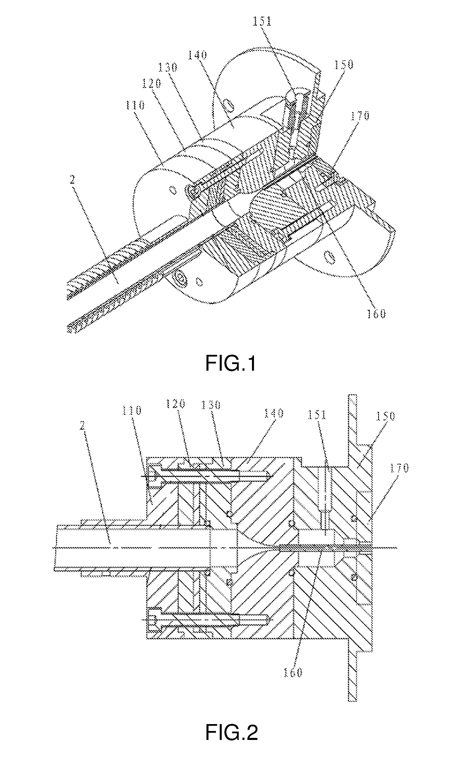
[0028]As shown in FIG. 1 and FIG. 2, a sheath flow device for ESLD which includes a fixing base for evaporating tube 110, a heat insulating part for evaporating tube 120, a sheath flow baffle 130, a sheath flow nozzle 140, a sheath flow sleeve 150 and a sheath flow outlet 170. The above mentioned six parts have the same internal diameter and are concentrically connected according to the mentioned order.

[0029]Thereinto, there is a seal ring respectively between the said heat insulating part for evaporating tube 120 and sheath flow baffle 130, the sheath flow baffle 130 and sheath flow nozzle 140, the sheath flow nozzle 140 and sheath flow sleeve 150.

[0030]All the said fixing base for evaporating tube 110, heat insulating part for evaporating tube 120, sheath flow baffle 130 and sheath flow nozzle 140 are cylinders with the same external diameter.

[0031]And the fixing base for evaporating tube 110, heat insulating part for evaporating tube 120, sheath flow baffle 130 and the sheath flo...


PUM

PropertyMeasurementUnit
external diameteraaaaaaaaaa
flow rateaaaaaaaaaa

Abstract

A sheath flow device for an evaporation light scattering detector comprises an evaporation pipe fastener (110), an evaporation pipe heat insulating component (120), a sheath flow nozzle blocking plate (130), a sheath flow nozzle (140), a sheath flow sleeve (150), a sheath flow outlet piece (170) and a stainless steel spray needle (160). The evaporation pipe fastener, the evaporation pipe heat insulating component, the sheath flow nozzle blocking plate, the sheath flow nozzle, the sheath flow sleeve and the sheath flow outlet piece are concentrically connected orderly from front to back, and all provided with concentric inner holes. Said device is applicable to ELSD sheath flow devices ranging from nanoliter-scale to microliter-scale. On one hand, material particles entering a testing pool are enveloped and aggregated so that the formation of eddy and turbulence can be reduced, the chromatographic peak shape of a sample can be improved and the stability of sample detection can be enhanced; on the other hand, the testing pool can be cleaned so that baseline noise can be reduced and the signal to noise ratio can be increased.

Description

BACKGROUND OF THE INVENTION[0001]This invention is concerned with evaporative light scattering detector (ELSD), especially concerned with a sheath-flow device for ELSD.[0002]ELSD is a universal and mass sensitive detector. It is not susceptible to molecular structure and spectroscopic properties of a compound. ELSD is suitable for detection of any compounds that have a lower volatility than the mobile phase, therefore, it can be used for volatile and semi-volatile compounds, especially suitable and powerful for detection and analysis of natural product, traditional Chinese medicine (TCM), lipid, surfactant and hydrocarbon, etc. Since ELSD has little effect on the peak broadening of micro-flow chromatography, it is suitable for any chromatographic techniques based on capillary column.[0003]Micro-fluid evaporative light-scattering detector (pELSD) is a miniaturized device that matches nano-liter to micro-liter / min flow of the mobile phase in a capillary chromatographic system. Its pri...

Claims


Application Information

Patent Timeline
Patent Type & Authority Applications(United States)
IPC IPC(8): G01N15/14G01N1/40
CPCG01N15/1404G01N2001/4027G01N2015/1409G01N1/4022G01N30/74G01N15/1459G01N15/1484G01N30/84G01N2030/8494G01N21/47G01N15/1409
Inventor YAN, CHAO
Owner YAN CHAO
Learn More